Add a Routing Rule
After adding a Routing Group, add a new Routing Rule to associate with the Group. Each Routing Rule is given a unique priority within the Routing Group. A rule listed higher than another, even if in the same Routing Group, takes precedence.
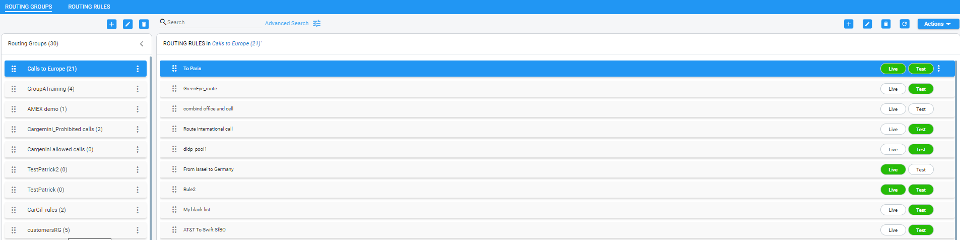
| ● | Routing rules are defined within Routing Groups. |
| ✔ | To view a specific Routing Group's Routing Rules, click that Group. |
| ✔ | To view all Routing Rules, click the Routing Rules tab. |
| ● | Any modification to the routing configuration (adding, deleting or modifying) takes effect within 60 seconds after the modification request is answered by the configurator and does not affect active calls. |
| ● | Any modification to routing logic because of an operational state change to a node or Peer Connection takes effect within 60 seconds after the status change is identified by the configurator. |
| ● | Any modification to routing logic because of a node or Peer Connection administrative state change takes effect within 60 seconds after the status change is identified by the configurator. |
| ● | Changes in users or user groups take effect within 60 seconds after the modification is identified by the configurator. |
Routing Rules include:
| ■ | Conditions: [Optional] Define the characteristics of the route request, e.g., the User Group and phone prefix of the originator/destination. |
| ■ | Actions: [Mandatory] Define actions performed if the call matches the rule conditions i.e., routes the call to the specified destination, or discards it specifying a SIP reason. |
Example of a Routing Rule
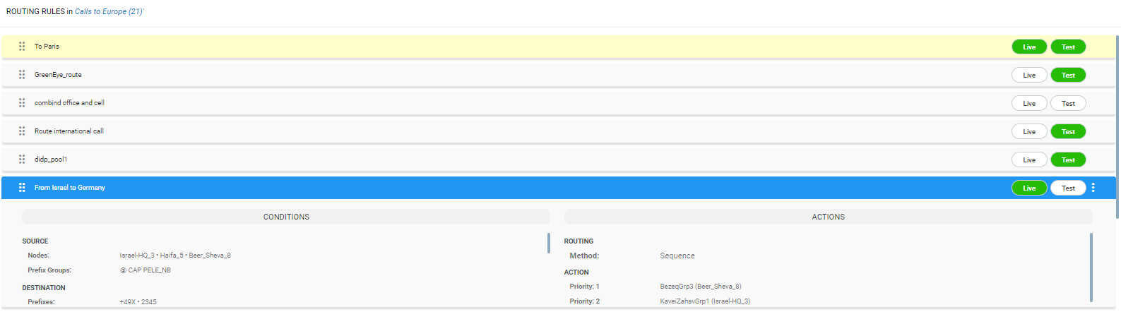
The ARM parses from the top Routing Group listed, to the bottom Routing Group listed, and within each Routing Group from the top Routing Rule listed to the bottom Routing Rule listed. If it finds a matching rule and if Nodes, Connections, Peer Connections and Resource Groups are available, it sends the call to the destination configured for that rule. If it doesn't find a matching rule, it indicates that a route for the call has not been found.
Alternative Routing
The ARM performs alternative routing as follows:
| ■ | The ARM attempts to build an alternative path for the same Routing Rule action (Nodes, Peer Connections, VoIP Peers and Resource groups), if available. For more information on Resource Groups, see Resource Groups Page Actions. |
| ■ | ARM attempts to build an alternative action (Nodes, Peer Connections, VoIP Peers and Resource groups), if available, for this call, in the order that actions are listed in the Routing Rule. For more information on Resource Groups, see Resource Groups Page Actions. |
| ■ | All routing alternatives are sorted by weighted path, cost and then by number of hops. |
Load Balancing
The ARM can balance call traffic between multiple destinations of the same Action. Call traffic can be distributed equally between destinations, or the distribution can be defined by the operator. Multiple routing attempts can be configured. Default: 1. Max: 3. The max can't exceed the number of destinations in the load balancing action. If a call to a destination configured in a load balancing action fails, the ARM will try to route it to one of the destinations configured in load balancing before searching for a new rule or action for it.
Registered users
The ARM can route a call only if the destination number is the number of a registered user in ARM (listed in the Registered Users table) and the Routing Rule is then matched.
Discard Call
The ARM can be configured to discard calls matching specific conditions as a single action, or as the last action of a rule if previous destinations were unavailable.
| ➢ | To add a new Routing Rule to a Routing Group: |
| 1. | In the Routing Groups page under the Routing Groups tab, select the Routing Group with which to associate the rule, and then click the Add Rule  icon. icon. |
This screen opens:
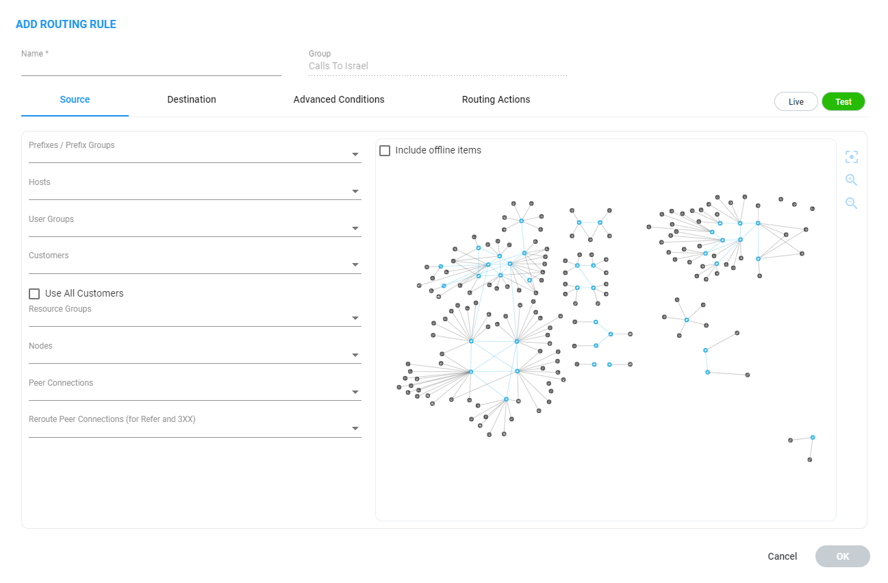
| 2. | Enter a name for the routing rule that is distinct from the names of the other routing rules in the same group. Define a user-friendly name to facilitate intuitive management by network administrators. The name can be between 1-255 characters. |
| 3. | Enable Live and/or Test mode. See Test a Route. |
| ● | Live. The rule will be taken into consideration for live calls traffic. |
| ● | Test. The route will be tested offline without impacting live calls traffic. |
By default, new routing rules are added with Test mode enabled and Live mode disabled. It is highly recommended to test the newly added routing rule before enabling it for live calls.
The following table shows the combinations that are supported for a Routing Rule:
Live | Test Mode Combinations
|
Live | Test Combination |
Explanation |
|---|---|
|
Live is enabled | Test is enabled |
The rule will be considered for both test and live traffic. |
|
Live is enabled | Test is disabled |
The rule will be considered only for live traffic. Test mode won't be impacted. Select this option to simulate rule removal. |
|
Live is disabled | Test is enabled |
The rule will only be considered only for test mode. Live traffic won't be impacted. Select this option to simulate and test a newly added rule. |
|
Live is disabled | Test is disabled |
The rule will not be considered for test nor live traffic. Select this option to prepare a Dial Plan. |
| 4. | Configure the settings under 'Source'. Use the following table as reference. |
Source Settings
| Setting | Description |
|---|---|
|
Prefixes/Prefix Groups |
Enter a source number prefix, or list of prefixes. You can also enter the name of a prefix group, or from the drop-down menu select a prefix group or list of prefix groups. |
|
Hosts |
Enter a source hostname, or list of hostnames. |
|
User Groups |
Enter the name of a source user group or list of source user groups, or select user groups from the drop-down menu. See Add Users Groups to the ARM. |
|
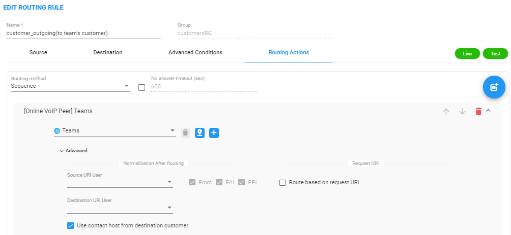
Allows you to select a ‘customer’ entity / set of ‘customer’ entities. From the drop-down, select a specific ‘customer’ entity or a set of ‘customer’ entities to be used to match the SOURCE field under the Advanced Conditions tab. Select the Use All Customers option for the rule to be applied to all ‘customer’ entitles (without selecting a specific ‘customer’ entity or a set of ‘customer’ entities). This is a very powerful functionality especially in the case of a very high number of ‘customer’ entities. In this way, with a single rule, you can define Calls Routing towards all the ‘customer’ entities with a Teams Peer VoIP Peer destination (action). This single rule will cover calls toward Teams for all ‘customer’ entities coming from several SBCs. Following is an example of a rule using Use All Customers in the Destination condition of a rule leading toward Teams.
In a Routing Rule’s ‘Routing Action’, check the Use Contact host from destination customer option under the ‘Advanced’ section of a specific action; in this case, the ARM automatically installs the value (string) provisioned in the SIP header field of the defined 'customer' entity into SIP Contact header of the invite designated to reach Teams.
|
|
|
Resource Groups |
From the drop-down, select a Resource Group. This setting is mandatory to define a routing rule applicable to specific call sources rather than (globally) to the entire network. Resource Groups comprise Nodes, Peer Connections and VoIP Peers. |
|
Nodes |
From the drop-down, select a source Node or Nodes, or select the element from the topology screen . This setting is mandatory to define a routing rule applicable to specific call sources rather than (globally) to the entire network. Note 1: To select multiple elements in the topology screen, press Ctrl and click the elements to select. Note 2: If the selected 'Nodes' or 'Peer Connections' or 'Reroute Peer Connections' or Topology group matches one of the conditions specified under the Advanced Conditions tab, the ARM will use this rule. |
|
Peer Connections |
From the drop-down, select a source Peer Connection or Peer Connections, or select the element from the topology screen shown in the figure following this table. This setting is mandatory to define a routing rule applicable to specific call sources rather than (globally) to the entire network. Note 1: To select multiple elements in the Choose Topology Item screen, press Ctrl and click the elements to select. Note 2: If the selected 'Nodes' or 'Peer Connections' or or 'Reroute Peer Connections' or Topology group matches one of the conditions specified under the Advanced Conditions tab, the ARM will use this rule. |
 Each ‘customer’ entity is identified / indicated by Teams with the FQDN in the ‘Contact’ or ‘From’ header. The call in the direction ‘to Teams’ should have this ‘Contact’ header identification as well. The ARM provides an easy way to put the predefined string (the one used by Teams to identify the tenant) in the Contact header for calls towards Teams.
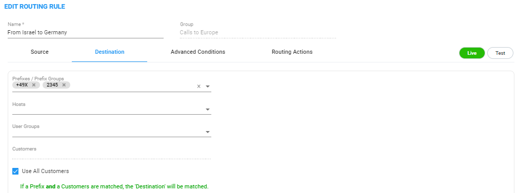
| 5. | In the Add Routing Rule screen, click Destination. |
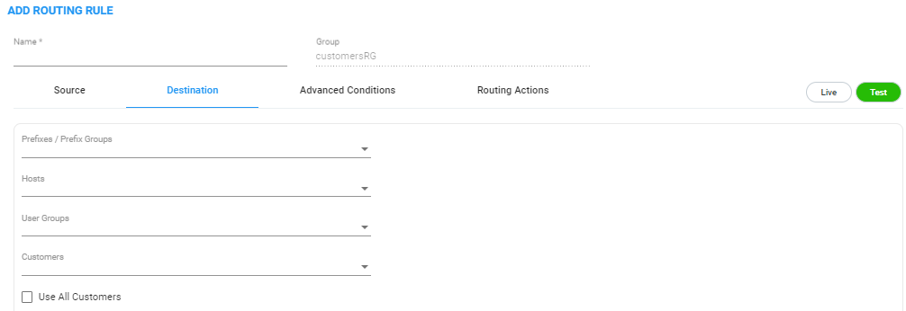
| 6. | Configure the 'Destination' settings using the following table as reference. |
Destination Settings
| Setting | Description |
|---|---|
|
Prefix/Prefix Groups |
Enter a destination number prefix, or list of prefixes. You can also enter the names of a prefix group or select prefix groups from the drop-down menu. |
|
Hosts |
Enter a destination hostname or list of hostnames. |
|
User Groups |
Enter the names of a user group, or list of destination user groups or select user groups from the drop-down menu. |
|
Customers |
See Customers. |
| 7. | In the Add Routing Rule screen, click Advanced Conditions. |
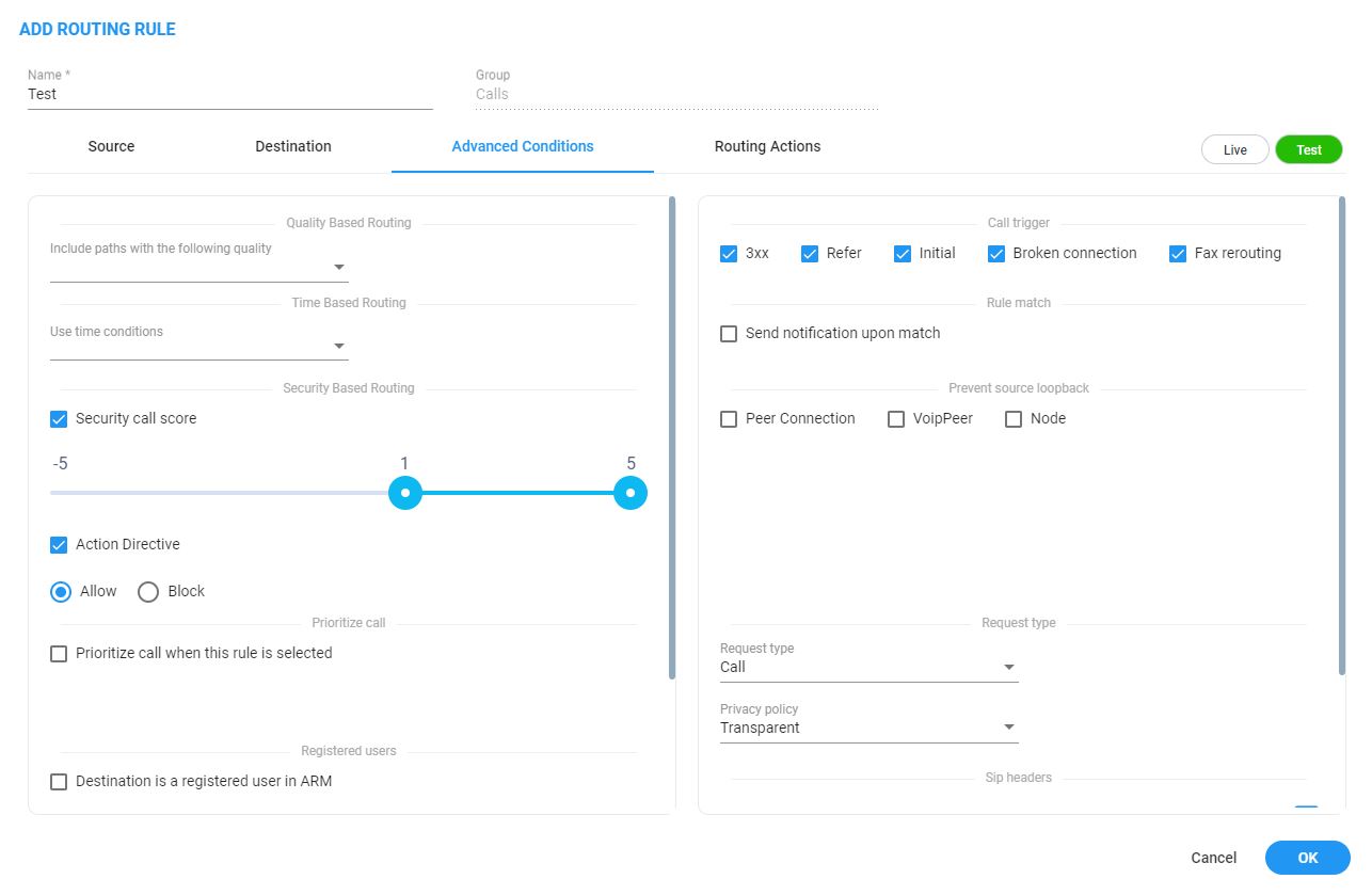
| 8. | Under 'Quality Based Routing', select the option include paths with the following quality; the drop-down menu becomes available. From it, select the quality criteria that you defined as shown in Routing Settings. Criteria for bad, fair and good quality, based on the calculation of MOS and ASR, can be defined. This screen lets you associate the criteria you defined with the Routing Rule. |
| 9. | Under 'Time based routing', select from the drop-down menu the time on which routing will be based, configured under Settings > Routing > Time Based Routing (see Routing Settings for information about configuring a time range). |
| ● | More than one Time Condition can be associated with the same Routing Rule. Activation of the Routing Rule is then performed in ‘or’ between Time Conditions. |
| ● | A Time Condition can be attached to a Routing Rule which belongs to a Routing Group with an already-associated period; the ARM's calculation of this Routing Rule's activation will then be ‘and’; the rule will be activated during the period assigned to the Routing Group and the period assigned to the Routing Rule. |
| 10. | Under Security Based Routing, select the Security call score and/or Action Directive options only if SecureLogix's Orchestra One™ CAS (Call Authentication Service) is used. The ARM supports security-based routing through integration with SecureLogix’s Orchestra One™ CAS. |
Using security-based routing requires purchasing SecureLogix’s license in addition to the ARM license and must be coordinated with AudioCodes.
Once Security call score is enabled, the Routing Rule will use the score returned from SecureLogix as part of the match. The slider is used to control the score threshold. If no score is returned from SecureLogix or the score doesn’t match the threshold, the rule will not be matched. Based on the score the ARM gets for a specific call, a routing decision is applied. Example:
| ● | For low-scoring calls (bad calls), the routing action may be ‘Drop call’. |
| ● | For average-scoring calls (suspicious calls), the network administrator can apply number manipulation and display the number with a ‘?’ or with the word ‘Suspicious’. |
The ARM features two strategy modes:
| ● | Standard mode. Calls are verified with the Orchestra One server with a low price. It checks for basic secure. Strategy is set to 0 and as read-only. |
| ● | Advanced. Calls are verified with the Orchestra One server with a higher price. For example: |
| ◆ | For Strategy value 1, Orchestra One will ‘Authenticate using the Verizon Call Verification Service (VCVS) when applicable’. |
| ◆ | Strategy is set to 1 and as user will be able to set it to 1 or higher. For Advanced mode, it’s typically necessary to enable the Sending SIP headers option. |
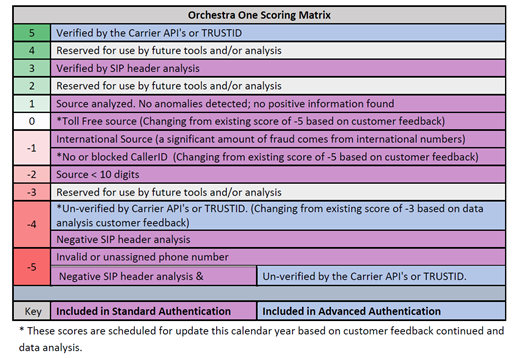
A call’s Security Score can be used as basis for a routing decision. Security-based routing can be applied to calls that receive a score from SecureLogix’s Orchestra One as part of the pre-routing process. The Routing Rule is applied to a specific range or to a certain value of the call security score received from the ARM ↔ Orchestra One consultation. The range is from -5 to 5.
ARM administrators may use the call’s security score as part of the routing decision. For example, calls to a specific (security-sensitive) destination with a score of less than 4 can be dropped, while calls to other destinations with a score of 4 can still be routed normally.
Operators can moreover apply number manipulation to the source call number and turn a source DID with a ‘suspicious’ security score into a question mark - which will draw the attention of the recipient of the call. The score description shown below is excerpted from the documentation of SecureLogix’s Orchestra One:
See also:
| ● | Web-based Services for information on how to configure an external web-based service |
| ● | Policy Studio for information on how to configure an external web-based service |
| ● | Activate Your License for information related to standard vs. advanced security |
| ● | View License Details for information related to standard vs. advanced security |
| 11. | Once 'Action Directive' is enabled, the Routing Rule uses the ‘action directive’ value returned from SecureLogix as part of the match. |
You can select one or more of the following Action Directive options; Allow, Block or Redirect.
| ● | If no Action Directive is returned from SecureLogix or the Action Directive value doesn’t match the Action Directive selected, the rule will not be matched. |
| ● | Alternatively, if the Action Directive value matches the Action Directive selected, the Routing Rule action will be performed. |
To drop a call that matches the Block option, define a Discard action.
To use the redirectTo phone number when the Redirect option is matched, define a SIP Manipulation Group in the Policy Studio (web-service type).
This SIP Manipulation Group will use a SIP Condition Group to:
| ● | Validate that Parm.SecureLogix.ActionDirective is equal to redirect. |
| ● | Check if Param.SecureLogix.RedirectTo exists. |
If the conditions are met, it will modify DestUri.User to the value of Param.SecureLogix.RedirectTo, effectively redirecting the call to the specified number.
The SecureLogix Call Authentication Service response depends on the ARM query. For using Action Directive, ARM needs two additional attributes to be included in its query to SecureLogix’s Orchestra One:
| ◆ | Customer ID |
| ◆ | Call Direction |
Configure these in the Edit Peer Connection screen. Use the figure below as reference:
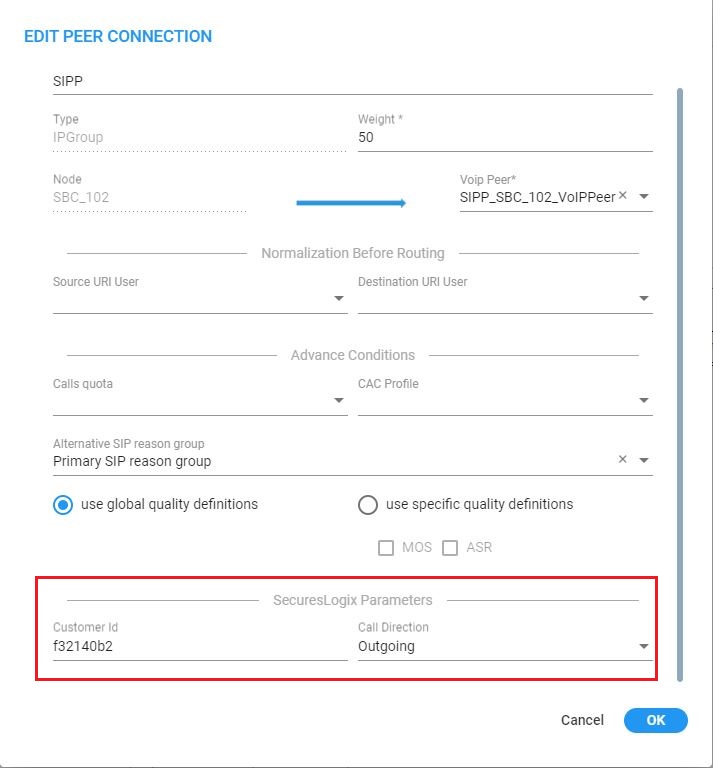
Use the table below as reference.
| Setting | Description |
|---|---|
|
Customer ID |
Customer identification string |
|
Call Direction |
Inbound (in) or outbound (out) |
| 12. | Select Prioritize call when this rule is selected to prioritize emergency calls over regular calls. The ARM supports emergency call preemption for SBC and gateway calls. If one of the devices is unavailable to process an emergency call because of lack of resources, a regular call will be preempted to free up resources so that the emergency call will be established. The ARM may preempt more than one active call to provide sufficient resources for processing the emergency call. Emergency calls can be identified by the matching rules parameters in the Add Routing Rule screen. |
| 13. | Under Registered Users, select Destination is a registered user in ARM; the routing rule will then be matched only if the destination number is a registered user number (listed in the Registered Users table). |
| 14. | Under ‘Advanced Conditions', select a Call Trigger to activate the rule for a specific Invite reason (i.e., alternative routing). By default, all 'Call Trigger' options are selected, so routing by default is based on all Call Triggers. At least one must be selected. The node applies to the ARM for a routing decision when it is triggered by another condition – such as a fax call or a Broken RTP connection. You can configure a rule to be triggered for example only for a fax call or for a ‘Refer call’. Call Trigger options are: |
| ● | 3xx [Re-routes the request if it was triggered because of a SIP 3xx response] |
| ● | REFER [Re-routes the INVITE if it was triggered because of a REFER request] |
| ● | Initial [This routing rule is used for regular requests that the device forwards to the destination] |
| ● | Broken Connection [If the Node detects a broken RTP connection during the call and the Broken RTP Connection feature is enabled in Pcon Ip-Profile (IP Profile > Broken Connection Mode = Reroute), you can use this option as an explicit matching characteristic to route the call to an alternative destination. Note that it's not supported for an incoming call from a third-party Pcon. |
| ● | Fax rerouting [This trigger will be used if the Node detects a call as a fax and the fax recognition feature is enabled on the Peer Connection. To enable the feature, the device Web interface's 'Routing Mode' parameter must be configured to Rerouting without delay (IP Profile > Rerouting Mode). Make sure this IP Profile is associated with the relevant IP Group. You can use this option as an explicit matching characteristic to route the call to an alternative fax destination. |
Fax call trigger is unsupported for incoming calls from third-party Peer Connection.
| 15. | Each rule is by default relevant in all circumstances because all Call Triggers are selected by default, but if you want to provide specific routing, for example, for fax calls only, select it as follows: |
Trigger/s Selected

In this case, the initial call is routed according to the generic Routing Rules (followed by the SIP Invite message). When the SBC categorizes this call as a fax call, another request for routing is sent to the ARM with the ‘Fax Rerouting’ trigger. This routing request matches another ARM Routing Rule dedicated for fax rerouting. In this way, you can route fax calls to a ‘Fax-to Mail’ server (for example).
| 16. | Under 'Rule match' , select Send notification upon match to enable a notification on a call (for example, a 911 emergency call) if the call matches a specific rule. |
When the ARM receives a call matching this rule condition, a notification (event) with related information is issued by the ARM Configurator. At the ARM level, the event can be sent to an SNMP target. With the ARM integrated into the OVOC, the call notification can trigger the issuance of an email by the OVOC, for example:
***** Event Info *****
Alarm Name: General Alarm
Date & Time: 09:24:16 AM September 6, 2018
Source: Router#172.17.113.23
Source Description:
Severity: info
Unique ID: 67
Alarm Type: other
Alarm Probable Cause: other
Description: Routing Rule 911 was matched
Additional Info 1:
Additional Info 2: Routing Rule "911" of Group "911" is matched.
Call from Pcon "Pcon Pcon-1" , Node "Node 16161104" - From number "+12345", To number "911".
Additional Info 3:
***** ARM Info *****
ARM IP Address 172.17.113.23
Notifications are typically required and used for 911 emergency calls, which should typically be reported via an email application or another notification application. The notification engine, however, can be used for any other matching rule.
| 17. | Under the screen section 'Prevent source loopback', check the elements for which you want to prevent source loopback. For example, if you check the Peer Connection option, the call will not be routed back to the source Peer Connection. |
In the case of a third-party node, the Peer Connection option is irrelevant.
| 18. | Optionally use the Routing Rule for routing registration messages: Configure (switch) the 'Request type' condition from its default Call to Register. |

You can define a dedicated set of Routing Rules for routing registration messages. The registration messages routing rules can be grouped in a separate dedicated Routing Group (or Groups). The 'Request type' condition differentiates between a Routing Rule to be used for call setup routing and a Routing Rule to be used for registration routing.
If you don't specify any other condition in the Routing Rule but you switch ‘Request type’ to Register, this routing rule will be applied to all the users defined as True (enabled) in their registration property, i.e., for all users allowed to route their registration messages. The operator can define multiple Routing Rules for registration messages based on conditions such as:
| ● | Source Node or Peer connection for registration messages coming from a specific topology element. |
| ● | Destination Prefix/Prefix group for a group of registration numbers. |
| ● | Destination User Groups for groups created with any sophisticated criteria with ARM users group facilities. |
| ● | Source URI taken from the SIP ‘To’ header. |
| ● | DEST URI taken from the SIP Request URI. |
| ● | Tag based. Very useful criterion. In the Policy Studio, you can assign a Tag to users based on a user’s Dictionary Attribute and route registrations to different SoftSwitches based on the Tag’s value. |
In the example below, the Routing Rule will be applied to users whose registration number starts with prefix 972 and who belong to the previously created Users Group ‘Imp. People’.
Routing Rule Example
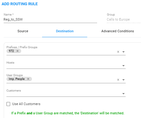
Note that not all conditions are relevant for routing of Registration messages. For example, conditions such as Source Prefix, Source Users Group or Call Trigger are not relevant.
| 19. | Under ‘Advanced Conditions' in the 'Privacy' section of the Edit Routing Rule screen, you can configure Calling Number Privacy. The ARM supports calling number privacy with different flavors (Privacy policy). The policy is applied per Routing Rule. |
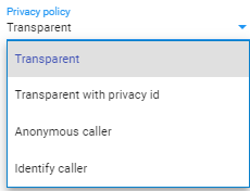
If a call matches the rule, the Privacy Policy is applied. Based on the Privacy Policy of the matching rule, the ARM instructs the SBC or Gateway how to handle calling number privacy in terms of SIP headers. Privacy Policy options are:
Privacy Policy Options
|
ARM Value |
SBC Value |
Comment |
||||||
|---|---|---|---|---|---|---|---|---|
|
Transparent |
[0] Transparent |
Default. Leave as is. |
||||||
|
Transparent with Privacy ID |
[1] Don't change privacy |
|
||||||
|
Anonymous caller |
[2] Restrict |
Turn the call into anonymous |
||||||
|
Identify caller |
[3] Remove Restriction |
|
| 20. | [Optional] You can route calls based on any SIP Invite header value as a Routing Rule matching criterion, for example, based on specific SDP information or on a TGRP value; any information present in the SIP Invite can be used as a condition in the ARM Routing Rule. The feature must be configured at both ARM and SBC level. |
| 21. | SIP Headers |
| ● | Configure the ‘name’ field, i.e., the SIP header name |
| ● | Configure the ‘value’ field, i.e., one or more possible values for rule match. The match within the same SIP header name is handled as OR and between the headers as AND. In the following ARM rule, the match is detected when the ARM gets X-ARM-DETAIL-X headers which include: (“tgrp=100” OR “tgrp=200”) AND (“coder=711” OR “coder=729”). |
When the SBC gets a new call (SIP Invite), it sends a REST routing request toward the ARM. This routing request includes parsed SIP information, for example, X-Header. In this way, using SBC-level manipulation, the X-Header can include any information operators want to pass to the ARM (for further routing decisions). This is the pre-agreed way to pass any SIP header information.
After applying SBC-level manipulation, the operator can configure ARM-level Routing Rules with a condition related to the required attributes and value (pre-installed using SBC-level manipulation).
The ARM is aware of the information followed by the preconfigured ‘X-ARM-DETAIL-N’ header and ready to use it for routing.
| 22. | [SBC-Level Configuration] To send a parsed information request, add a new header with name “X-ARM-DETAIL-1”, “X-ARM-DETAIL-2”… “X-ARM-DETAIL-N” and with information inside taken from the SDP or any other SIP header. X-ARM-DETAIL-X format is “X-ARM-DETAIL-1:<name=value>” |
For example:
| ● | X-ARM-DETAIL-1: “tgrp=100” |
| ● | X-ARM-DETAIL-2: “coder=711” |
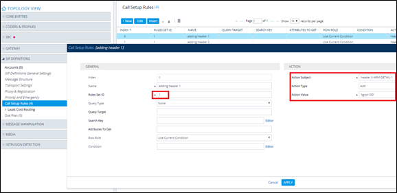
To create a new header in the SBC, add a new ‘Call Setup Rules Set ID’ in ‘IPGroup’ or in ‘SIP Interface’ in the device’s Web interface. The figure below shows ‘IPGroup’.
[Web Interface] Call Setup Rules Set ID
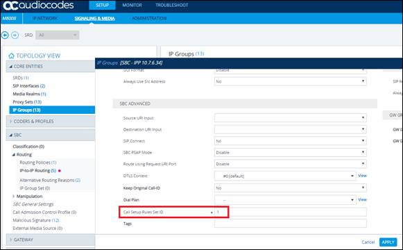
Setup rules can then be associated with the same Set ID. In the following figure, the manipulation added is ‘tgrp=100’. In general, you can use a condition with RegEx and take the attributes into the Action Value.
[Web Interface] Viewing SBC Call Setup Rules Configuration
| 23. | In the ARM’s Add Routing Rule screen, click Routing Actions. |
Routing Actions
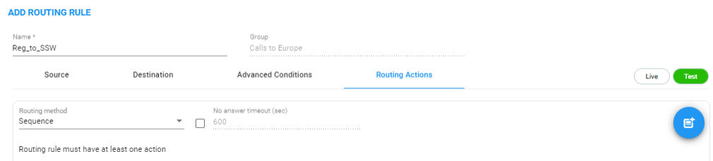
| 24. | From the ‘Routing method’ drop-down, select Sequence or Forking. |
The parameter ‘Routing method’ is configured by default to Sequence; Routing Rule Actions are applied sequentially (the only option in ARM versions earlier than 8.6).
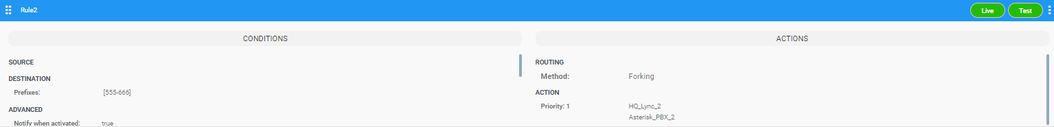
If you configure ‘Routing method’ to Forking, the actions are applied simultaneously and the call is split to all the destinations. The ARM supports calls forking at a network level. SIP forking refers to the process of ‘forking’ a single SIP call to multiple SIP endpoints. A single call can be split to many endpoints at the same time. The first extension (SIP end-point) to pick up the call receives the call; all other extensions then stop ringing.
Forking implementation in the ARM is designed to split specific calls (matching preconfigured condition) between several network-wide destinations (Peer Connections, VoIP Peers or nodes). Forking is integrated into ARM Routing Rules logic. Forking is applied if a call matches the Routing Rule condition.
Forking implementation in ARM utilizes SBC forking capabilities. When a call matches an ARM routing rule condition with forking, the ARM instructs the SBC to perform forking per the actions configured in ARM Routing Rule.
The ARM supports up to three forking legs (different actions). If one or more of the actions with Forking Routing methods includes load balancing between multiple destinations, the load balancing (with configured percentages) will be applied to choose the correct destination of the forking leg.
Forking
| ● | When upgrading from an earlier ARM version than 8.6, all Routing Rules are translated with the Sequence routing method (the default). |
| ● | In the ARM, forking capabilities can only be applied to SBCs. Media Gateways aren’t supported. |
| ● | Forking in the ARM is supported on SBC software 7.20.252 GA or later (release pending). For earlier SBC versions, Forking functions like ‘Sequence’. |
| 25. | Select the No answer timeout option; if the called party does not answer a call within this given interval, the device will disconnect the session. Clear the option for the device to use the default value. The option allows management of the SBC/Gateway’s timeout feature for no answer. The option controls the SBC/Gateway ‘No answer timeout’. |
The option is available only for the ‘sequence’ routing method.
The feature gives the ARM the capability of managing delayed call forking. If the number is dialed and there is no call pickup after the configured timeout, the call is forked.
| 1. | Under ‘Routing Actions’, navigate to and choose the 'Add action' + option. |

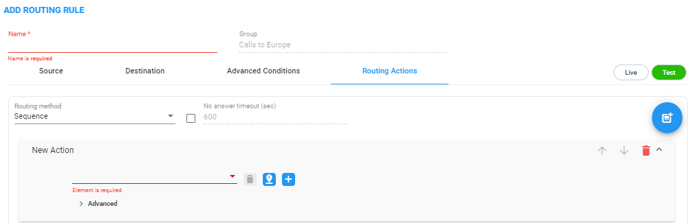
| a. | Select from the drop-down menu the Peer Connection, VoIP Peer, node or Resource Group to which the call will be routed; the list is categorized; best practice is to scroll down the list to the category and then select the element. |
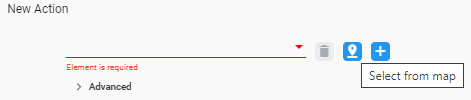
Alternatively, click the 'Select from map' icon and in the topology screen that opens select the VoIP Peer, Peer Connection or Node. In large networks with high numbers of topology elements, this visual method of selecting the topology element may prevent human error from occurring and facilitate precise selection.
If a Resource Group is selected for an action, a 'Resource Attempts' option is displayed.
| b. | Configure the number of 'Resource attempts', i.e., the number of elements the ARM will try before going to the next action. The maximum number of attempts that can be configured = the number of elements in the Resource Group. |
| c. | Click Advanced to open post routing (after routing) normalization. |
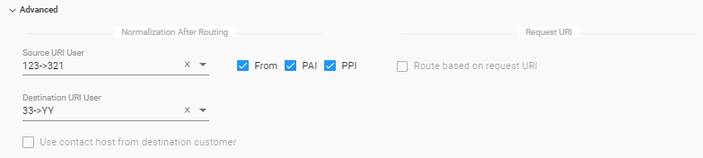
| ◆ | From the 'Source URI User' drop-down, select the source element (see Add a Normalization Group) to manipulate the source number in the outgoing call to the Peer Connection. The source normalization group can only be connected to an IP Group or VoIP Peer. It cannot be connected to a node. |
Source URI manipulation for a specific field, either the ‘From’ field, the ‘PAI’ field or the ‘PPI’ field, can be applied.
By default, all three fields are checked when you apply a manipulation to Source URI users. Prior to ARM 9.2, this was the only available behavior. From ARM 9.2, you can check a specific field and clear the others. The functionality is valid for post-routing only. It's supported per Action.
You can also test a call with a manipulation of a specific Source URI header, using the Test Route feature extension (support for a specific SIP header simulation). For more information, see Test a Route.
| ◆ | From the 'Destination URI User' drop-down, select the destination element (see Add a Normalization Group) to manipulate the destination number in the outgoing call to the Peer Connection. The destination normalization group can only be connected to an IP Group or VoIP Peer. It cannot be connected to a Node. |
| 2. | Optionally select the Route based on request URI check box under the ‘Request URI’ section (under section ‘Normalization After Routing’) to enable combined ARM and SIP based routing decisions on a per-action basis, for when a customer (or a customer’s network) provides routing instructions for a call as part of the SIP INVITE message (via REQUEST URI). The Peer Connection (the SBC’s IP Group) must be specified in the action as well. SIP based routing takes place in the context of a specific SBC and IP Group. In this way, the ARM will route a call until a specified SBC and request the SBC to use ‘REQUEST URI’ for further routing. The feature is available for SBCs only. |
| 3. | Click the 'Add load balancing' button; the screen adds the following items: |
| ● | Equally Balance option (selected by default) |
| ● | 'Routing Attempts' field |
| ● | Drop-down field for selecting Peer Connection, VoIP Peer or Node with an 'Add load balancing' button located next to it |
Load Balancing
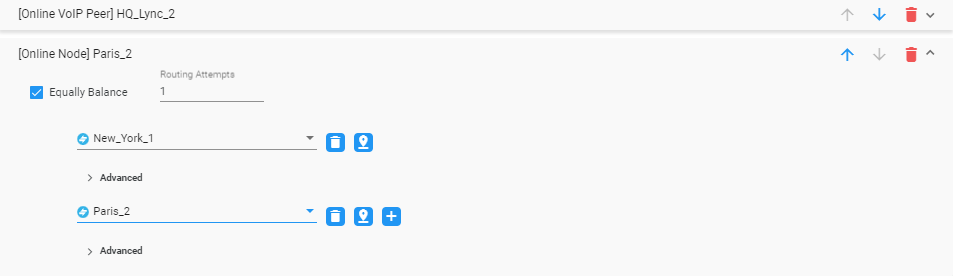
Load balancing is added between more than one Peer Connection, Node, VoIP Peer or Resource Group. By default, these are equally balanced, i.e., the same percentage is assigned for each option.
| 4. | (Optional) Clear the Equally Balance check box to define your own percentage. Any distribution can be chosen, i.e., any percentage of calls can be handled by a specific routing option. Several routing destinations (more than two) are supported by using the 'Add load balancing' button. |
| 5. | Enter the percentage of routes that will take this action when load balancing is configured and Equally Balance is cleared. Make sure you have 100% in the Action's calls destinations summary else you won't be allowed to enable the action. |
| 6. | Configure the parameter 'Routing Attempts' as shown in the following figure. The maximum attempts that can be configured is 3. Default: 1. The maximum number of 'Routing Attempts' can't exceed the number of destinations in the action; see for example the action [Online Node] PARIS_2 in the following figure. |
Equally Balance: Routing Attempts = 2
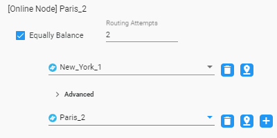
The 'Routing Attempts' parameter determines the number of attempts that will be made within the load balancing action. If load balancing is configured within a Routing Rule's Action and a call to a destination configured in this Action fails for some reason, the ARM will try to route the call to one of the destinations configured in load balancing before searching for a new rule or action for the call.
| 7. | Click > Advanced in order to apply number manipulation on the Source URI and / or the Destination URI. |
| ● | To remove a Peer Connection, Node, VoIP Peer or Resource Group, click the adjacent trash can. |
| ● | To remove an entire action, click the trash can on the right side of the screen. |
| 8. | (Optional) Click the Route to user location button  |
Route to user location
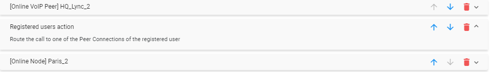
The ARM will now attempt to route the call to the location of the registered user (the destination number is used as the key to search for the location).
The ARM supports forking for registered users. If the Routing Rule’s 'Routing Method' is set to 'Forking' and the action is set to ‘Registered Users’ (‘Route to user location’), the ARM will attempt to apply forking if the same user is registered in multiple SBCs.
| 9. | (Optional) Add a discard action by clicking the 'Add discard action' icon. |
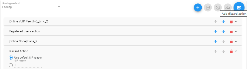
In a routing rule, you can apply a policy to attempt multiple routing options and to discard the call if none succeed. The action 'Discard Action' can be used - in addition to other routing actions of the same rule - as a last routing rule action or as a sole action.
| 10. | Configure the discard action using the following as reference. |
Discard Action
| Setting | Description |
|---|---|
|
Use default SIP reason |
Select the default SIP reason (the last SIP reason received from the SBC or the Gateway) or provide a specific SIP reason as shown in the next parameter description.. |
|
SIP Reason |
Select this option for a specific SIP reason to be returned to the source peer connection when rejecting the call. Must be a valid SIP reason. |
If any field is left empty (Prefix Group/Host/User Group/Node/Peer Connection), the rule will not check it.
| 11. | Click the 'Add stop ARM routing action' (and continue with node’s internal routing). This feature enables a combined routing decision taken by the ARM and a node (SBC only). The feature enables customers to specify that after a specific number of routing attempts configured in ARM routing, they’d like to continue with the local SBC routing table. The ARM supports the action in the Routing Rule: Stop ARM routing. A second action follows this: Stop ARM routing and continue with node’s internal routing table. This action is always the last option in a Routing Rule. The feature is only available for SBC nodes. |
Continue with Node's internal routing table
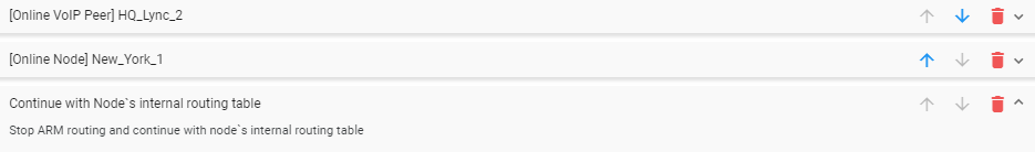
The feature additionally allows current AudioCodes SBC customers who want to use ARM Security-based Routing (integrated with SecureLogix) without immediately moving to the ARM. These customers can use ARM’s SecureLogix integration feature but must indicate in their routing rule that the calls must be routed based on the SBC’s existing routing table. ARM routing capabilities can be provisioned in future.
Fields such as 'Nodes', 'Peer Connections' and 'User Groups' in the Add Routing Rule screens and Edit Routing Rule screens feature filters in which network administrators can select multiple elements and then invert the selection. The feature improves usability and user experience especially in large networks with high numbers of elements. The feature allows network administrators to
| ● | Select a single element |
| ● | Delete a single element (x) |
| ● | Select All elements |
| ● | Clear all selected elements |
| ● | Select All and delete a few (x) |
| ● | Select All, delete a few (x) and then invert the selection; the elements deleted will be in the selection |
| ● | Select a few elements and then invert the selection; only elements that weren’t selected will be in the selection |
| ● | Clear a selection |