Viewing Call Details
To display the details of a call, select a call whose details you wish to view and then click Show. The figures below display example details for a call.
| ● | Call Quality is not measured for PSTN legs, only for IP legs. Signaling and Trends tabs are displayed when a call is connected and media is transferred. |
| ● | The SBC device should be configured to send QoE Reports and Call Flow messages. |
Media CDR Fields
|
Parameters |
Description |
||||||
|---|---|---|---|---|---|---|---|
|
Media IP Address |
|
||||||
|
Media Port |
|
||||||
|
Burst Duration |
The mean duration (in milliseconds), of the burst periods that have occurred since the initial call reception. |
||||||
|
Rx Rate |
Shows the call's reception rate, in Kbps. |
||||||
|
Quality |
Voice quality: Good (green), Fair (yellow) or Red (poor). |
||||||
|
MOS |
MOS - MeanOpinion Score (specified by ITU-T recommendation P.800) - the average grade on quality scales of Good to Failed, given to voice calls madeover a VoIP network at the conclusion of the testing. |
||||||
|
Jitter (msec) |
Jitter can result from uneven delays between received voice packets. To space packets evenly, the jitter buffer adds delay. The higher the measurement, the greater the impact of the jitter buffer’s delay on audio quality. Two Jitter values are shown, one value for the caller side andone value for the callee side. |
||||||
|
Packet Loss (%) |
Lost packets - RTP packets that aren’t received by the voice endpoint for processing, resulting in distorted voice transmission. Two Packet Loss % values are shown, one value for the caller side and one value for the callee side. Packet Loss can be more than 100%. |
||||||
|
Delay (msec) |
Delay (or latency) - the time it takes for information to travel from source to destination (round-trip time). Sources of delay include voice encoding / decoding, link bandwidth and jitter buffer depth. Two Delay values are shown, one value for the caller side andone value for the callee side. |
||||||
|
Media Cluster |
Displays the name and index of the Media Cluster interface reported by the device. Example: , where n following the displayed name is the number indicating the Media Cluster's index used to facilitate network configuration. | ||||||
|
Media IF |
Displays the name and index of the Media Realm interface reported by the device. Example: SIMcmxLAN (n), where n following the displayed name is the number indicating the Media Interface's index used to facilitate network configuration. |
||||||
|
Network IF |
Network Interface Name. |
||||||
|
Coder |
Up to 10 coders (per group) are supported. See the device manual for a list of supported coders. |
||||||
|
SCE |
Method for conserving bandwidth on VoIP calls by not sending packets when silence is detected. True = Enabled (On), False = Disabled (Off). |
||||||
|
RTP Direction |
RTP Directional Control. Controlled internally by the device according to the selected coder. |
||||||
|
RTCP Direction |
RTCP Directional Control. Controlled internally by the device according to the selected coder. |
||||||
|
PTime (msec) |
Packetization time, i.e., how many coder payloads are combined into a single RTP packet. |
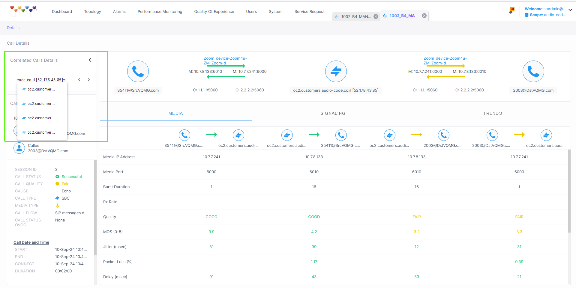
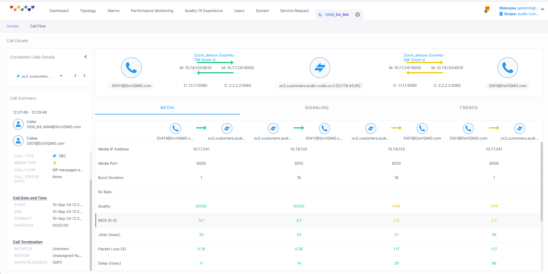
Call Media
The Call Media tab displays the media related CDR data that is retrieved from the SBC device.
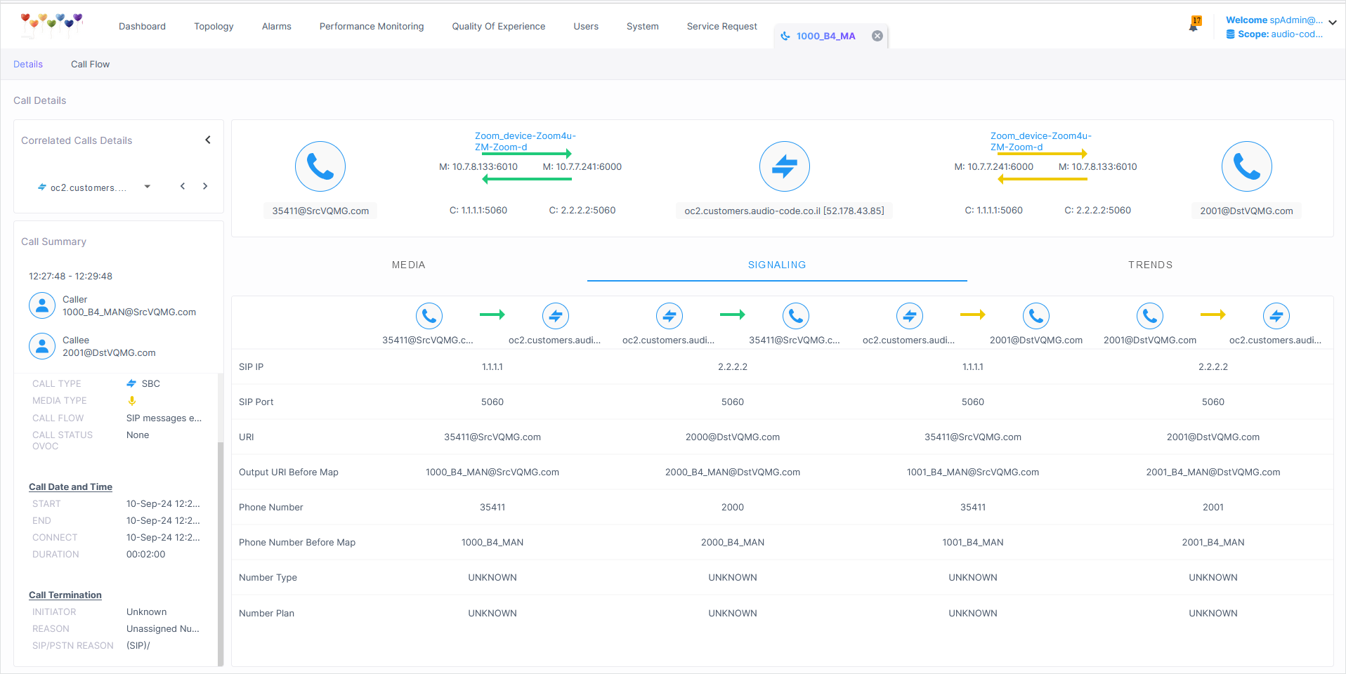
The Call Signaling tab displays the Call Signaling CDR information that is retrieved from the SBC device.
Call Signaling
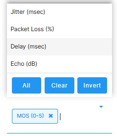
The Call Trends page tab displays calculated metrics data displayed across a timeline. You can toggle to display data for different metrics.
Call Trends
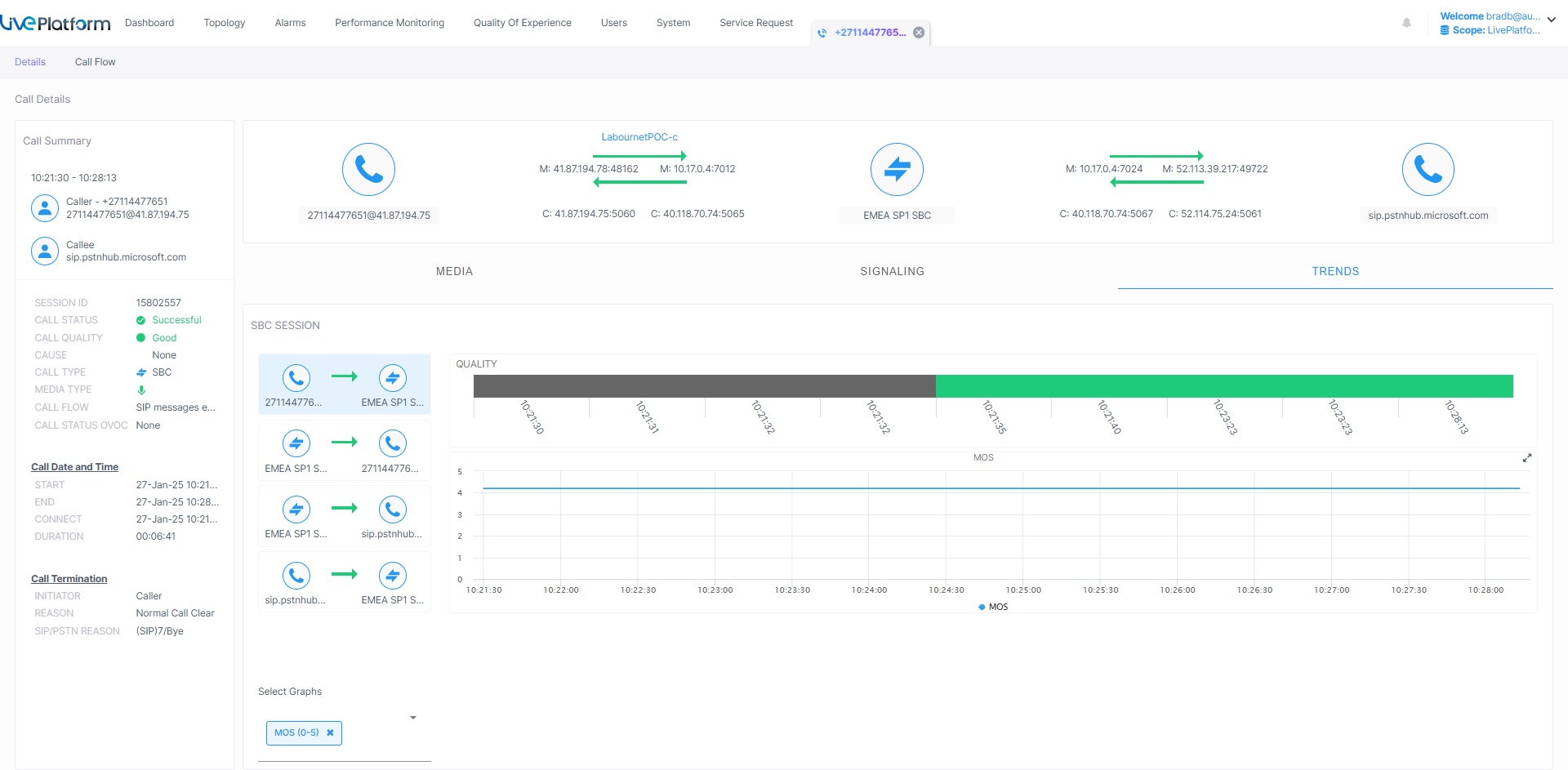
Open the Select Graphs drop-down to toggle to display different metrics.
The following table describes the CDR fields that are retrieved from the SBC.
Signaling CDR Parameters
|
Parameters |
Description |
|---|---|
|
SIP IP |
The destination IP address. The field is a string of up to 20 characters. |
|
SIP Port |
The SIP signaling destination UDP port. The field is an integer of up to 10 digits. |
|
URI |
The destination URI (username@host) after manipulation, if any. The field is a string of up to 150 characters. |
|
Output URI Before Map |
The original destination URI (username@host) before manipulation, if any. The field is a string of up to 150 characters. |
|
Phone Number |
The destination phone number. |
|
Phone Number Before Map |
The original destination number (before manipulation, if any). |
|
Number Type |
The destination Type of Number (TON). |
|
Number Plan |
The destination Numbering Plan Identification (NPI). |
|
The following parameters are displayed when a device is attached to a Hybrid device. |
|
|
Endpoint Type |
The type of endpoint. For example, 'SBC'. |
|
SRD |
The unique name and index configured for the signaling routing domain (SRD). Example: someSRD (n), where n following the displayed name is the number indicating the SRD's index used to facilitate network configuration. |
|
IP Group |
The ID of the IP Group with which the call is associated. |
|
Proxy Set |
The Proxy Set to which the call is associated. This is a group of Proxy servers. Typically, for IP-to-IP call routing, at least two are defined for call destination – one for each leg (IP Group) of the call (i.e., both directions). For example, one Proxy Set for the Internet Telephony Service provider (ITSP) interfacing with one 'leg' of the device and another Proxy Set for the second SIP entity (e.g., ITSP) interfacing with the other 'leg' of the device. |
|
SIP IF |
The ID of the SIP Interface with which the call is associated. |
|
IP Profile |
The IP Profile assigned to this IP destination call. The IP Profile assigns numerous configuration attributes (e.g., voice codes) per routing rule. |
|
Transport Type |
Two options: UDP or TCP |
|
Signaling Diff Server |
The value for Premium Control CoS content (Call Control applications). |
|
Trunk Group Number |
The Trunk Group number or name (configured in the Trunk Group Settings table) that is added to the 'tgrp' parameter value in the Contact header of outgoing SIP messages. |
|
B-Channel Number |
The B-channel number used as the calling number (sent in the From field of the INVITE) instead of the number received in the Q.931 Setup message, for Tel-to-IP calls. |
|
Call ID |
The unique call identification (SIP Call-ID header value) contained in the SIP header messages. |
The following figure shows Call Details for a Correlated call. From the drop-down box, toggle between call legs to display call details for each leg.