|
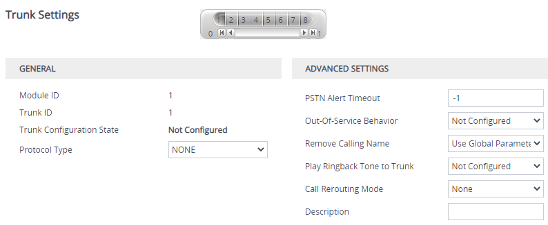
General
|
|
'Module ID'
|
(Read-only) Displays the module number to which the trunk belongs.
|
|
'Trunk ID'
|
(Read-only) Displays the selected trunk ID number.
|
|
'Trunk Configuration State'
|
(Read-only) Displays the status of the trunk:
|
■
|
"Not Configured": The trunk is not configured. |
|
■
|
"Active": The trunk is configured and currently active. |
|
■
|
"Inactive": The trunk is configured, but was stopped and is inactive (not operational). |
|
|
'Protocol Type'
configure voip > interface e1-t1|bri > protocol
[ProtocolType]
|
Defines the PSTN protocol for the specific trunk.
|
■
|
[1] E1 EURO ISDN = ISDN PRI Pan-European (CTR4) protocol
|
|
■
|
[2] T1 CAS = Common T1 robbed bits protocols including E&M wink start, E&M immediate start, E&M delay dial/start and loop-start and ground start.
|
|
■
|
[4] T1 TRANSPARENT = Transparent protocol, where no signaling is provided by the device. Timeslots 1 to 24 of all trunks are mapped to DSP channels.
|
|
■
|
[5] E1 TRANSPARENT 31 = Transparent protocol, where no signaling is provided by the device. Timeslots 1 to 31 of each trunk are mapped to DSP channels.
|
|
■
|
[6] E1 TRANSPARENT 30 = Transparent protocol, where no signaling is provided by the device. Timeslots 1 to 31, excluding time slot 16 of all trunks are mapped to DSP channels.
|
|
■
|
[7] E1 MFCR2 = Common E1 MFC/R2 CAS protocols (including line signaling and compelled register signaling).
|
|
■
|
[8] E1 CAS = Common E1 CAS protocols (including line signaling and MF/DTMF address transfer).
|
|
■
|
[10] T1 NI2 ISDN = National ISDN 2 PRI protocol
|
|
■
|
[11] T1 4ESS ISDN = ISDN PRI protocol for the Lucent™/AT&T™ 4ESS switch.
|
|
■
|
[12] T1 5ESS 9 ISDN = ISDN PRI protocol for the Lucent™/AT&T™ 5ESS-9 switch.
|
|
■
|
[13] T1 5ESS 10 ISDN = ISDN PRI protocol for the Lucent™/AT&T™ 5ESS-10 switch.
|
|
■
|
[14] T1 DMS100 ISDN = ISDN PRI protocol for the Nortel™ DMS switch.
|
|
■
|
[16] T1 NTT ISDN = ISDN PRI protocol for the Japan - Nippon Telegraph Telephone (known also as INS 1500).
|
|
■
|
[17] E1 AUSTEL ISDN = ISDN PRI protocol for the Australian Telecom.
|
|
■
|
[18] E1 HKT ISDN = ISDN PRI (E1) protocol for the Hong Kong - HKT.
|
|
■
|
[19] E1 KOR ISDN = ISDN PRI protocol for Korean Operator (similar to ETSI).
|
|
■
|
[20] T1 HKT ISDN = ISDN PRI (T1) protocol for the Hong Kong - HKT.
|
|
■
|
[21] E1 QSIG = ECMA 143 QSIG over E1
|
|
■
|
[22] E1 TNZ = ISDN PRI protocol for Telecom New Zealand (similar to ETSI)
|
|
■
|
[23] T1 QSIG = ECMA 143 QSIG over T1
|
|
■
|
[30] E1 FRENCH VN6 ISDN = France Telecom VN6
|
|
■
|
[31] E1 FRENCH VN3 ISDN = France Telecom VN3
|
|
■
|
[34] T1 EURO ISDN =ISDN PRI protocol for Euro over T1
|
|
■
|
[35] T1 DMS100 Meridian ISDN = ISDN PRI protocol for the Nortel™ DMS Meridian switch
|
|
■
|
[36] T1 NI1 ISDN = National ISDN 1 PRI protocol
|
|
■
|
[40] E1 NI2 ISDN = National ISDN 2 PRI protocol over E1
|
Note:
|
■
|
If you are modifying the parameter for an already configured trunk through the Web interface, stop the trunk prior to configuring it. |
|
■
|
All PRI trunks must be configured with the same protocol type (E1 or T1). The device can support different variants of CAS and PRI protocols on different E1/T1 spans (no more than four simultaneous PRI variants).
|
|
|
Trunk Configuration
|
|
'Clock Master'
configure voip > interface e1-t1 > clock-master
[ClockMaster]
|
Defines the Tx clock source of the E1/T1 line.
|
■
|
[0] Recovered = (Default) Generates the clock according to the Rx of the E1/T1 line.
|
|
■
|
[1] Generated = Generates the clock according to the internal TDM bus.
|
Note:
|
■
|
If you are modifying the parameter for an already configured trunk through the Web interface, first stop the trunk. |
|
■
|
To configure the source of the internal TDM bus clock, see the [TDMBusClockSource] parameter.
|
|
■
|
The parameter is applicable only to E1/T1 interfaces.
|
|
|
'Auto Clock Trunk Priority'
configure voip > interface e1-t1|bri > clock-priority clock-priority
[AutoClockTrunkPriority]
|
Defines the trunk priority for auto-clock fallback for the specific trunk.
The valid range is 0 to 100, where 0 (default) is the highest priority and 100 indicates that the device doesn't perform a fallback to the trunk (typically used to mark untrusted source of clock).
Note:
|
■
|
If you are modifying the parameter for an already configured trunk through the Web interface, first stop the trunk. |
|
■
|
To enable auto-clock fallback, configure the [TDMBusPSTNAutoClockEnable] parameter to 1. |
|
|
'Line Code'
configure voip > interface e1-t1 > line-code
[LineCode]
|
Defines the line code for the specific trunk.
|
■
|
[0] B8ZS = (Default) B8ZS line code (applicable only to T1 trunks).
|
|
■
|
[1] AMI = AMI line code.
|
|
■
|
[2] HDB3 = HDB3 line code (applicable only to E1 trunks).
|
|
■
|
If you are modifying the parameter for an already configured trunk through the Web interface, first stop the trunk. |
|
■
|
The parameter is applicable only to E1/T1 trunks. |
|
|
'Line Build Out Loss'
configure voip > interface e1-t1 > line-build-out-loss
[LineBuildOut.Loss]
|
Defines the line build out loss for the specific trunk.
Note:
|
■
|
If you are modifying the parameter for an already configured trunk through the Web interface, first stop the trunk. |
|
■
|
The parameter is applicable only to T1 trunks.
|
|
|
'Trace Level'
configure voip > interface e1-t1|bri > trace-level
[TraceLevel]
|
Defines the trace level for the specific trunk.
|
■
|
[3] Only ISDN Q.931 Messages Trace |
|
■
|
[4] Layer 3 ISDN No Duplication Trace |
|
|
'Framing Method'
configure voip > interface e1-t1 > framing
[FramingMethod]
|
Defines the physical framing method for the specific trunk.
|
■
|
[0] Extended Super Frame = (Default) Depends on protocol type:
|
|
✔
|
E1: E1 CRC4 MultiFrame Format extended G.706B (same as c)
|
|
✔
|
T1: T1 Extended Super Frame with CRC6 (same as D)
|
|
■
|
[1] Super Frame = T1 SuperFrame Format (as B).
|
|
■
|
[a] E1 FRAMING DDF = E1 DoubleFrame Format - CRC4 is forced to off
|
|
■
|
[b] E1 FRAMING MFF CRC4 = E1 CRC4 MultiFrame Format - CRC4 is always on
|
|
■
|
[c] E1 FRAMING MFF CRC4 EXT = E1 CRC4 MultiFrame Format extended G.706B - auto negotiation is on. If the negotiation fails, it changes automatically to CRC4 off (ddf)
|
|
■
|
[A] T1 FRAMING F4 = T1 4-Frame multiframe.
|
|
■
|
[B] T1 FRAMING F12 = T1 12-Frame multiframe (D4).
|
|
■
|
[C] T1 FRAMING ESF = T1 Extended SuperFrame without CRC6
|
|
■
|
[D] T1 FRAMING ESF CRC6 = T1 Extended SuperFrame with CRC6
|
|
■
|
[E] T1 FRAMING F72 = T1 72-Frame multiframe (SLC96)
|
|
■
|
[F] T1 FRAMING ESF CRC6 J2 = J1 Extended SuperFrame with CRC6 (Japan)
|
|
|
ISDN Configuration
|
|
'ISDN Termination Side'
configure voip > interface e1-t1|bri > isdn-termination-side
[TerminationSide]
|
Defines the ISDN termination side for the specific trunk.
|
■
|
[0] User side = (Default) ISDN User Termination Equipment (TE) side. |
|
■
|
[1] Network side = ISDN Network Termination (NT) side. |
Note:
|
■
|
For clock synchronization of E1/T1 interfaces, to configure if the clock is recovered (from the line) or generated (by the device), see the 'Clock Master' parameter (above). |
|
✔
|
If the parameter is configured to User side, the clock is recovered from the line. |
|
■
|
If you are modifying the parameter for an already configured trunk through the Web interface, first stop the trunk.
|
|
■
|
Select User side when the PSTN or PBX side is configured as Network side, and vice versa. If you don't know the device's ISDN termination side, select User side. If the D-channel alarm is indicated, choose Network side. |
|
|
'Q.931 Layer Response Behavior'
configure voip > interface bri|e1-t1 > isdn-bits-ns-behavior
[ISDNIBehavior]
|
Defines (by bit-field) several behavior options that influence the behavior of the Q.931 protocol.
|
■
|
[0] = Disable (default). |
|
■
|
[1] NO STATUS ON UNKNOWN IE = Q.931 Status message isn't sent if Q.931 received message contains an unknown/unrecognized IE. By default, the Status message is sent.
Note: This value is applicable only to ISDN variants in which sending of Status message is optional. |
|
■
|
[2] NO STATUS ON INV OP IE = Q.931 Status message isn't sent if an optional IE with invalid content is received. By default, the Status message is sent.
Note: This option is applicable only to ISDN variants in which sending of Status message is optional. |
|
■
|
[4] ACCEPT UNKNOWN FAC IE = Accepts unknown/unrecognized Facility IE. Otherwise, the Q.931 message that contains the unknown Facility IE is rejected (default).
Note: This option is applicable only to ISDN variants where a complete ASN1 decoding is performed on Facility IE. |
|
■
|
[128] SEND USER CONNECT ACK = The Connect ACK message is sent in response to received Q.931 Connect; otherwise, the Connect ACK is not sent.
Note: This option is applicable only to Euro ISDN User side outgoing calls. |
|
■
|
[512] EXPLICIT INTERFACE ID = Enables configuration of T1 NFAS Interface ID. For more information on NFAS, see the [ISDNNFASInterfaceID_x] parameter.
Note: This value is applicable only to 4/5ESS, DMS, NI-2 and HKT variants.
|
|
■
|
[2048] ALWAYS EXPLICIT = Always set the Channel Identification IE to explicit Interface ID, even if the B-channel is on the same trunk as the D-channel.
Note: This value is applicable only to 4/5ESS, DMS and NI-2 variants. |
|
■
|
[32768] ACCEPT MU LAW =Mu-Law is also accepted in ETSI. |
|
■
|
[65536] EXPLICIT PRES SCREENING = The calling party number (octet 3a) is always present even when presentation and screening are at their default.
Note: This option is applicable only to ETSI, NI-2, and 5ESS. |
|
■
|
[131072] STATUS INCOMPATIBLE STATE = Clears the call on receipt of Q.931 Status with incompatible state. Otherwise, no action is taken (default). |
|
■
|
[262144] STATUS ERROR CAUSE = Clear call on receipt of Status according to cause value. |
|
■
|
[524288] ACCEPT A LAW =A-Law is also accepted in 5ESS. |
|
■
|
[2097152] RESTART INDICATION = Upon receipt of a Restart message, acEV_PSTN_RESTART_CONFIRM is generated. |
|
■
|
[4194304] FORCED RESTART = On data link (re)initialization, send RESTART (Class 7) if there is no call. |
|
■
|
[67108864] NS ACCEPT ANY CAUSE = Accept any Q.850 Cause IE from ISDN.
Note: This option is applicable only to Euro ISDN. |
|
■
|
[536870912] QSI ACCEPT ALCATEL FAC = Alcatel coding for redirect number and display name is accepted by the device.
Note: This option is applicable only to QSIG (and relevant for specific Alcatel PBXs such as OXE). |
|
■
|
[1073741824] QSI ENCODE INTEGER = If this bit is set, INTEGER ASN.1 type is used in operator coding (compliant to new ECMA standards); otherwise, OBJECT IDENTIFIER ASN.1 type is used.
Note: This option is applicable only to QSIG. |
|
■
|
[2147483648] 5ESS National Mode For Bch Maintenance = Use the National mode of AT&T 5ESS for B-channel maintenance. |
Note:
|
■
|
If you are modifying the parameter for an already configured trunk through the Web interface, first stop the trunk.
|
|
■
|
When configuring through the Web interface, click the arrow button and then for each required option select 1 to enable. |
|
■
|
When configuring through ini file, to support multiple behaviors, configure the parameter with a summation of the individual feature values. For example, to support both [512] and [2048] features, configure the parameter to 2560 (i.e., 512 plus 2048). |
|
|
'Outgoing Calls Behavior'
configure voip > interface bri|e1-t1
> isdn-bits-outgoing-calls-behavior
[ISDNOutCallsBehavior]
|
Defines (by bit-field) several options that influence the behavior of the ISDN Stack outgoing calls. To select the options, click the arrow button, and then for each required option, select 1 to enable. The default is 0 (i.e., disabled).
|
■
|
[2] USER SENDING COMPLETE =The default behavior of the device (when this bit is not set) is to automatically generate the Sending-Complete IE in the Setup message. This behavior is used when overlap dialing is not needed. When overlap dialing is needed, set this bit and the behavior is changed to suit the scenario, i.e., Sending-Complete IE is added when required in the Setup message for Enblock mode or in the last Digit with Overlap mode. |
|
■
|
[16] USE MU LAW = The device sends G.711-m-Law in outgoing voice calls. When disabled, the device sends G.711-A-Law in outgoing voice calls. |
Note: This option is applicable only to the Korean variant.
|
■
|
[128] DIAL WITH KEYPAD = The device uses the Keypad IE to store the called number digits instead of the CALLED_NB IE. |
Note: This option is applicable only to the Korean variant (Korean network). This is useful for Korean switches that don't accept the CALLED_NB IE.
|
■
|
[256] STORE CHAN ID IN SETUP = The device forces the sending of a Channel-Id IE in an outgoing Setup message even if it's not required by the standard (i.e., optional) and no Channel-Id has been specified in the establishment request. This is useful for improving required compatibility with switches.On PRI lines it indicates an unused channel ID, preferred only. |
|
■
|
[512] USE A LAW = The device sends G.711 A-Law in outgoing voice calls. When disabled, the device sends the default G.711-Law in outgoing voice calls.
|
Note: The option is applicable only to the E10 variant (T1 ISDN).
|
■
|
[1024] = Numbering plan/type for T1 IP-to-Tel calling numbers are defined according to the manipulation tables or according to the RPID header (default). Otherwise, the plan/type for T1 calls are set according to the length of the calling number.
|
Note: The option is applicable only to T1 ISDN.
|
■
|
[2048] = The device accepts any IA5 character in the called_nb and calling_nb strings and sends any IA5 character in the called_nb, and is not restricted to extended digits only (i.e., 0-9,*,#). |
|
■
|
[16384] DLCI REVERSED OPTION = Behavior bit used in the IUA interface groups to indicate that the reversed format of the DLCI field must be used. |
Note:
|
■
|
If you are modifying the parameter for an already configured trunk through the Web interface, first stop the trunk.
|
|
■
|
When configuring through ini file, to support multiple options, enter a summation of the individual feature values. For example, to support both [2] and [16] features: ISDNOutCallsBehavior = 18 |
|
|
'Incoming Calls Behavior'
configure voip > interface e1-t1|bri > isdn-bits-incoming-calls-behavior
[ISDNInCallsBehavior]
|
Defines (by bit-field) several options that influence how the ISDN Stack INCOMING calls behave.
|
■
|
[32] DATA CONN RS = The device automatically sends a Q.931 Connect (answer) message on incoming Tel calls (Q.931 Setup). |
|
■
|
[64] VOICE CONN RS = The device sends a Connect (answer) message on incoming Tel calls. |
|
■
|
[2048] CHAN ID IN FIRST RS = The device sends Channel ID in the first response to an incoming Q.931 Call Setup message. If not set, the Channel ID is sent only if the device requires changing the proposed Channel ID. |
|
■
|
[4096] USER SETUP ACK = (Default) The Setup Ack message is sent by the SIP Gateway application layer and not automatically by the PSTN stack. |
|
■
|
[8192] CHAN ID IN CALL PROC = The device sends Channel ID in a Q.931 Call Proceeding message. |
|
■
|
[65536] PROGR IND IN SETUP ACK = (Default) The device includes Progress Indicator (PI=8) in Setup Ack message if an empty called number is received in an incoming Setup message. This option is applicable to the overlap dialing mode. The device also plays a dial tone (for TimeForDialTone) until the next called number digits are received. |
|
■
|
[2147483648] USER SCREEN INDICATOR = When the device receives two Calling Number IE's in the Setup message, the device, by default, uses only one of the numbers according to the following: |
|
✔
|
Network provided, Network provided: first calling number is used |
|
✔
|
Network provided, User provided: first calling number is used |
|
✔
|
User provided, Network provided: second calling number is used |
|
✔
|
User provided, user provided: first calling number is used |
When this bit is configured, the device behaves as follows:
|
✔
|
Network provided, Network provided: first calling number is used |
|
✔
|
Network provided, User provided: second calling number is used |
|
✔
|
User provided, Network provided: first calling number is used |
|
✔
|
User provided, user provided: first calling number is used |
Note:
|
■
|
If you are modifying the parameter for an already configured trunk through the Web interface,first stop the trunk.
|
|
■
|
In the Web interface, the parameter displays the summation of the enabled optional bit values in hex format. For example, the default value is 0x11000 (69632 in decimal), which is a summation of the two bit options, USER SETUP ACK (0x01000 or 4096 in decimal) and PROGR IND IN SETUP ACK (0x10000 or 65536 in decimal) that are enabled by default (i.e., 4096 + 65536 = 69632). |
|
■
|
When configuring through ini file, to support multiple options, enter a summation of the individual feature values. For example, to support both [2048] and [65536] features: ISDNInCallsBehavior = 67584 |
|
|
'General Call Control Behavior'
configure voip > interface e1-t1|bri > isdn-bits-cc-behavior
[ISDNGeneralCCBehavior]
|
Defines (by bit-field) several general CC behavior options. To select the options, click the arrow button, and then for each required option, select 1 to enable. The default is 0 (i.e., disabled).
|
■
|
[2] = Data calls with interworking indication use 64 kbps B-channels (physical only). |
|
■
|
[8] REVERSE CHAN ALLOC ALGO = Channel ID allocation algorithm. |
|
■
|
[16] = The device clears down the call if it receives a NOTIFY message specifying 'User-Suspended'. A NOTIFY (User-Suspended) message is used by some networks (e.g., in Italy or Denmark) to indicate that the remote user has cleared the call, especially in the case of a long distance voice call. |
|
■
|
[32] CHAN ID 16 ALLOWED = Applies only to ETSI E1 lines (30B+D). Enables handling the differences between the newer QSIG standard (ETS 300-172) and other ETSI-based standards (ETS 300-102 and ETS 300-403) in the conversion of B-channel ID values into timeslot values:
|
|
✔
|
In 'regular ETSI' standards, the timeslot is identical to the B-channel ID value, and the range for both is 1 to 15 and 17 to 31. The D-channel is identified as channel-id #16 and carried into the timeslot #16.
|
|
✔
|
In newer QSIG standards, the channel-id range is 1 to 30, but the timeslot range is still 1 to 15 and 17 to 31. The D-channel is not identified as channel-id #16, but is still carried into the timeslot #16.
When this bit is set, the channel ID #16 is considered as a valid B-channel ID, but timeslot values are converted to reflect the range 1 to 15 and 17 to 31. This is the new QSIG mode of operation. When this bit is not set (default), the channel_id #16 is not allowed, as for all ETSI-like standards.
|
|
■
|
[64] USE T1 PRI = PRI interface type is forced to T1.
|
|
■
|
[128] USE E1 PRI = PRI interface type is forced to E1.
|
|
■
|
[256] START WITH B CHAN OOS = B-channels start in the Out-Of-Service state (OOS). |
|
■
|
[512] CHAN ALLOC LOWEST = CC allocates B-channels starting from the lowest available B-channel id. |
|
■
|
[1024] CHAN ALLOC HIGHEST = CC allocates B-channels starting from the highest available B-channel id. |
|
■
|
[4096] NO B CHANEL CONTROL = When this bit is set, B-channels allocation and control is left according to the application level. Call control doesn't control / allocate B-channels. The application provides the B-channel information within the appropriate ACU primitives. Call Control simply provides the received Channel-ID IE contents to the user, without checking its availability, validity or consistency with other calls in progress. This bit should be set when the B-channel can be changed in Q.931 Proceeding, Alerting, or Connect. |
|
■
|
[16384] CC_TRANSPARENT_UUI = The UUI-protocol implementation of CC is disabled allowing the application to freely send UUI elements in any primitive, regardless of the UUI-protocol requirements (UUI Implicit Service 1). This allows more flexible application control on the UUI. When this bit is not set (default behavior), CC implements the UUI-protocol as specified in the ETS 300-403 standards for Implicit Service 1. |
|
■
|
[65536] GTD5 TBCT = CC implements the VERIZON-GTD-5 Switch variant of the TBCT Supplementary Service, as specified in FSD 01-02-40AG Feature Specification Document from Verizon. Otherwise, TBCT is implemented as specified in GR-2865-CORE specification (default behavior). |
Note:
|
■
|
If you are modifying the parameter for an already configured trunk through the Web interface, first stop the trunk.
|
|
■
|
When configuring through ini file, to support multiple options, enter a summation of the individual feature values. For example, to support both [16] and [32] features: ISDNGeneralCCBehavior = 48 |
|
|
'ISDN NS Behaviour 2'
configure voip > interface e1-t1|bri > isdn-bits-ns-extension-behavior
[ISDNNSBehaviour2]
|
Defines (by bit-field) several options that influence the behavior of the Q.931 protocol for the specific trunk.
|
■
|
[8] NS BEHAVIOUR2 ANY UUI = Any User to User Information Element (UUIE) is accepted for any protocol discriminator. This is useful for interoperability with non-standard switches. |
|
■
|
[16] NS BEHAVIOUR2 DISPLAY = The Display IE is accepted even if it is not defined in the QSIG ISDN protocol standard. This is applicable only when configuration is QSI. |
|
■
|
[64] NS BEHAVIOUR2 FAC REJECT = When this bit is set, the device answers with a Facility IE message with the Reject component on receipt of Facility IE with unknown/invalid Invoke component. This bit is implemented in QSIG and ETSI variants. |
|
■
|
[256] RESTART CLASS 7 IN FORCE RESTART = When this bit is set, the device sends RESTART (Class 7) if there is no call, on data link (re)initialization. |
|
|
'NFAS Group Number'
configure voip > interface e1-t1 > isdn-nfas-group-number
[NFASGroupNumber]
|
Defines the ISDN Non-Facility Associated Signaling (NFAS) group number (NFAS member) for the specific trunk.
|
■
|
[0] 0 = (Default) Non-NFAS trunk.
|
|
■
|
[1-12] 1 to 12 = NFAS group number.
|
Trunks belonging to the same NFAS group have the same number. With NFAS, you can use a single D-channel to control multiple PRI interfaces.
Note:
|
■
|
If you are modifying the parameter for an already configured trunk through the Web interface, first stop the trunk.
|
|
■
|
For the parameter to take effect, a device restart is required.
|
|
■
|
The parameter is applicable only to T1 ISDN protocols.
|
|
|
'NFAS Interface ID'
configure voip > interface e1-t1 > isdn-nfas-interface-id
[ISDNNFASInterfaceID]
|
Defines a different Interface ID for the specific trunk.
The valid range is 0 to 100. The default interface ID equals the trunk's ID.
Note:
|
■
|
If you are modifying the parameter for an already configured trunk through the Web interface, first stop the trunk.
|
|
■
|
To set the NFAS interface ID, configure the [ISDNIBehavior_x] parameter to include '512' feature per T1 trunk.
|
|
■
|
The parameter is applicable only to T1 ISDN protocols.
|
|
|
'D-channel Configuration'
configure voip > interface e1-t1 > isdn-nfas-dchannel-type
[DChConfig]
|
Defines the specific trunk as primary, backup (optional), or B-channel.
|
■
|
[0] PRIMARY= (Default) Primary Trunk - contains a D-channel that is used for signaling.
|
|
■
|
[1] BACKUP = Backup Trunk - contains a backup D-channel that is used if the primary D-channel fails.
|
|
■
|
[2] NFAS = NFAS Trunk - contains only 24 B-channels, without a signaling D-channel.
|
Note:
|
■
|
If you are modifying the parameter for an already configured trunk through the Web interface, first stop the trunk.
|
|
■
|
The parameter is applicable only to T1 ISDN protocols. |
|
|
CAS Configuration
|
|
'Dial Plan'
configure voip > interface e1-t1 > cas-dial-plan-name
[CASTrunkDialPlanName_x]
|
Defines the CAS Dial Plan name for the specific trunk.
The range is up to 11 characters.
For example, the following configures an E1_MFCR2 trunk with a single protocol (Trunk 5):
ProtocolType_5 = 7
CASFileName_0='R2_Korea_CP_ANI.dat'
CASTableIndex_5 = 0
DialPlanFileName = 'DialPlan_USA.dat'
CASTrunkDialPlanName_5 = 'AT_T'
|
|
'CAS Table per Trunk'
configure voip > interface e1-t1 > cas-table-index
[CASTableIndex_x]
|
Defines the CAS protocol for the specific trunk from a list of CAS protocols defined by the parameter CASFileName_x.
For example, the below configuration specifies Trunks 0 and 1 to use the E&M Winkstart CAS (E_M_WinkTable.dat) protocol, and Trunks 2 and 3 to use the E&M Immediate Start CAS (E_M_ImmediateTable.dat) protocol:
CASFileName_0 = 'E_M_WinkTable.dat'
CASFileName_1 = 'E_M_ImmediateTable.dat'
CASTableIndex_0 = 0
CASTableIndex_1 = 0
CASTableIndex_2 = 1
CASTableIndex_3 = 1
Note: To configure CAS tables per B-channel, see the [CASChannelIndex] parameter.
|
|
'CAS Table per Channel'
configure voip > interface e1-t1 > cas-channel-index
[CASChannelIndex]
|
Defines the loaded CAS protocol table index per B-channel pertaining to a CAS trunk. The parameter is assigned a string value and can be set in one of the following two formats:
|
■
|
CAS table per channel: Each channel is separated by a comma and the value entered denotes the CAS table index used for that channel. The syntax is <CAS index>,<CAS index> (e.g., "1,2,1,2…"). For this format, 31 indices must be defined for E1 trunks (including dummy for B-channel 16), or 24 indices for T1 trunks. Below is an example for configuring a T1 CAS trunk (Trunk 5) with several CAS variants: |
ProtocolType_5 = 7
CASFILENAME_0='E_M_FGBWinkTable.dat'
CASFILENAME_1='E_M_FGDWinkTable.dat'
CASFILENAME_2='E_M_WinkTable.txt'
CasChannelIndex_5 = ‘0,0,0,1,1,1,2,2,2,0,0,0,1,1,1,0,1,2,0,2,1,2,2,2’
CASDelimitersPaddingUsage_5 = 1
|
■
|
CAS table per channel group: Each channel group is separated by a colon and each channel is separated by a comma. The syntax is <x-y channel range>:<CAS table index>, (e.g., "1-10:1,11-31:3"). Every B-channel (including 16 for E1) must belong to a channel group. Below is an example for configuring an E1 CAS trunk (Trunk 5) with several CAS variants: |
ProtocolType_5 = 8
CASFILENAME_2='E1_R2D'
CASFILENAME_7= E_M_ImmediateTable_A-Bit.txt'
CasChannelIndex_5 = ‘1-10:2,11-20:7,21-31:2’
Note:
|
■
|
To configure the parameter, first stop the trunk. |
|
■
|
Only one of these formats can be implemented (not both). |
|
■
|
When the parameter is not configured, a single CAS table is used for the entire trunk (configured by the [CASTableIndex] parameter). |
|
|
Advanced Settings
|
|
'PSTN Alert Timeout'
configure voip > interface e1-t1|bri > pstn-alrt-timeout
[TrunkPSTNAlertTimeout]
|
Defines the Alert Timeout (ISDN T301 timer) in seconds for outgoing calls to PSTN for the specific trunk. This timer is used between the time that an ISDN Setup message is sent to the Tel side (IP-to-Tel call establishment) and a Connect message is received. If Alerting is received, the timer is restarted.
The range is 1 to 600. The default is 180.
|
|
'Local ISDN Ringback Tone Source'
configure voip > interface e1-t1|bri > local-isdn-rbt-src
[LocalISDNRBSource]
|
Defines if the ringback tone is played to the ISDN by the PBX/PSTN or by the device for the specific trunk.
|
■
|
[0] PBX = (Default) PBX/PSTN plays the ringback tone. |
|
■
|
[1] Gateway = The device plays the ringback tone. |
Note: The parameter is used together with the [PlayRBTone2Trunk] parameter.
|
|
'Set PI in Rx Disconnect Message'
configure voip > interface e1-t1|bri > pi-in-rx-disc-msg
[PIForDisconnectMsg]
|
Defines the device's behavior for the specific trunk when a Disconnect message is received from the ISDN before a Connect message is received.
|
■
|
[-1] Not Configured = (Default) Sends a 183 SIP response according to the received progress indicator (PI) in the ISDN Disconnect message. If PI = 1 or 8, the device sends a 183 response, enabling the PSTN to play a voice announcement to the IP side. If there isn't a PI in the Disconnect message, the call is released. |
|
■
|
[0] No PI = Doesn't send a 183 response to IP. The call is released. |
|
■
|
[1] PI = 1 = Sends a 183 response to IP. |
|
■
|
[8] PI = 8 = Sends a 183 response to IP. |
|
|
'ISDN Transfer Capabilities'
configure voip > interface e1-t1|bri > isdn-xfer-cab
[ISDNTransferCapability]
|
Defines the IP-to-ISDN Transfer Capability of the Bearer Capability IE in ISDN Setup messages for the specific trunk (where the x in the ini file parameter name denotes the trunk number and where 0 is Trunk 1).
|
■
|
[0] Audio 3.1 (default) |
Note: If the parameter is not configured or configured to Not Configured, Audio 3.1 capability is used.
|
|
'Progress Indicator to ISDN'
configure voip > interface e1-t1|bri > pi-to-isdn
[ProgressIndicator2ISDN]
|
Defines the Progress Indicator (PI) in ISDN messages that are sent to the PSTN for the specific trunk.
|
■
|
[-1] Not Configured = (Default) The PI in ISDN messages is set according to the [PlayRBTone2Tel] parameter. |
|
■
|
[0] No PI = PI is not sent to ISDN. |
|
■
|
[1] PI = 1 = The PI value is sent to PSTN in Q.931/Proceeding and Alerting messages. Typically, the PSTN/PBX cuts through the audio channel without playing local ringback tone, enabling the originating party to hear remote Call Progress Tones or network announcements. |
|
■
|
[2] PI = 2 = The PI value is sent to PSTN in Q.931/Proceeding and Alerting messages. The destination address is non-ISDN. |
|
■
|
[8] PI = 8 = The PI value is sent to PSTN in Q.931/Proceeding and Alerting messages. Typically, the PSTN/PBX cuts through the audio channel without playing local ringback tone, enabling the originating party to hear remote Call Progress Tones or network announcements. |
|
|
'Select Receiving of Overlap Receiving'
configure voip > interface e1-t1|bri > ovrlp-rcving-type
[ISDNRxOverlap]
|
Defines the receiving (Rx) type of ISDN overlap dialing for Tel-to-IP calls for the specific trunk.
|
■
|
[0] None = (Default) Disabled. |
|
■
|
[1] Local receiving = ISDN Overlap Dialing - the complete number is sent in the INVITE Request-URI user part. The device receives ISDN called number that is sent in the 'Overlap' mode. The ISDN Setup message is sent to IP only after the number (including the Sending Complete IE) is fully received (via Setup and/or subsequent Info Q.931 messages). In other words, the device waits until it has received all the ISDN signaling messages containing parts of the called number, and only then it sends a SIP INVITE with the entire called number in the Request-URI. |
|
■
|
[2] Through SIP = Interworking of ISDN Overlap Dialing to SIP according to RFC 3578. The device sends the first received digits from the ISDN Setup message to the IP side in the initial INVITE message. For each subsequently received ISDN Info Q.931 message, the device sends the collected digits to the IP side in re-INVITE messages. |
|
■
|
[3] Through SIP INFO = Interworking of ISDN Overlap Dialing to SIP according to RFC 3578. The device sends the first received digits from the ISDN Setup message to the IP side in the initial INVITE message. For each subsequently received ISDN Info Q.931 message, the device sends the collected digits to the IP side in INFO messages. |
Note:
|
■
|
When configured to Through SIP or Through SIP INFO, you can configure the minimum number of overlap digits to collect before sending the first SIP message for routing the call, using the [MinOverlapDigitsForRouting] parameter. |
|
■
|
When configured to Through SIP or Through SIP INFO, even if SIP 4xx responses are received during this ISDN overlap receiving, the device doesn't release the call. |
|
■
|
The [MaxDigits] parameter can be used to limit the length of the collected number for ISDN overlap dialing (if Sending Complete is not received). |
|
■
|
If a digit map pattern is defined (using the [DigitMapping] or [DialPlanIndex] parameters), the device collects digits until a match is found (e.g., for closed numbering schemes) or until a timer expires (e.g., for open numbering schemes). If a match is found (or the timer expires), the digit collection process is terminated even if Sending Complete is not received. |
|
■
|
To enable ISDN overlap dialing for IP-to-Tel calls, use the [ISDNTxOverlap] parameter. |
|
|
'B-Channel Negotiation'
configure voip > interface e1-t1|bri > b-channel-nego-for-trunk
[BChannelNegotiationForTrunk]
|
Defines the ISDN B-channel negotiation mode for the specific trunk.
|
■
|
[-1] Not Configured = (Default) The negotiation mode is according to the global parameter [BChannelNegotiation]. |
Note: The Any option is applicable only if you configure the 'ISDN Termination Side' parameter to User side.
|
|
'Out-Of-Service Behavior'
configure voip > interface bri|e1-t1 > dig-oos-behavior
[DigitalOOSBehaviorForTrunk_x]
|
Defines the method for setting the trunk to out-of-service state for the specific trunk. The parameter is applicable to the Busy Out feature (see the [EnableBusyOut] parameter) and the Lock/Unlock per Trunk Group feature performed in the Trunk Group Settings table of the Web interface.
|
■
|
[-1] Not Configured = (Default) The out-of-service method is according to the global parameter [DigitalOOSBehavior].
|
|
✔
|
ISDN: Sends ISDN Service messages to indicate out-of-service or in-service state for ISDN variants that support Service messages. For ISDN variants that do not support Service messages, the device sends an Alarm Indication Signal (AIS) alarm.
|
|
✔
|
CAS: Sends an Alarm Indication Signal (AIS) alarm.
|
|
■
|
[1] Service =
(Applicable only to T1 ISDN variants that support this method)Sends ISDN Service messages indicating out-of-service or in-service state.
|
|
✔
|
Graceful out-of-service disabled: The device rejects new incoming calls and immediately takes all channels (idle and busy) out-of-service, by sending Service messages on the B-channels. The device disconnects busy channels before it sends out-of-service Service messages on them.
|
|
✔
|
Graceful out-of-service enabled: The device rejects new incoming calls. If at least one busy channel exists during the graceful period, the device immediately takes all idle channels out-of-service and sends out-of-service Service messages to the other B-channels as soon as they become idle. When graceful period ends, the device disconnects all non-idle channels and then sends out-of-service Service messages to them.
|
When connectivity is restored for the Busy Out feature or the Trunk Group is unlocked, the device brings all the trunks back into service by sending in-service Service messages to all their B-channels.
|
■
|
[2] D-Channel = (Applicable only to ISDN and fully configured trunks) Takes the D-channel down or brings it up.
|
|
✔
|
Graceful out-of-service disabled: The device rejects new incoming calls and immediately takes the D-channel down.
|
|
✔
|
Graceful out-of-service enabled: The device rejects new incoming calls. Only when all channels are idle (when graceful period ends or when all channels become idle before graceful period ends, whichever occurs first), does the device take the D-channel down.
|
When connectivity is restored for the Busy Out feature or the Trunk Group is unlocked, the device brings the D-channels up again.
Note: For partially configured trunks (only some channels configured), this option only rejects new calls for the trunk; the D-channel remains up.
|
■
|
[3] Alarm = Sends or clears a PSTN Alarm Indication Signal (AIS) alarm.
|
|
✔
|
Graceful out-of-service disabled: The device rejects new incoming calls and immediately sends an AIS alarm.
|
|
✔
|
Graceful out-of-service enabled: The device rejects new incoming calls and only when all channels are idle (when graceful period ends or when all channels become idle before graceful period ends, whichever occurs first), does the device send an alarm on the trunk.
|
When connectivity is restored for the Busy Out feature or the Trunk Group is unlocked, the device clears the alarm.
Note: For partially configured trunks (only some channels configured), this option only rejects new calls for the trunk; no alarm is sent.
|
■
|
[4] Block = (Applicable only to CAS) Blocks the B-channels.
|
|
✔
|
Graceful out-of-service disabled: The device rejects new incoming calls and immediately blocks all channels (idle and busy). The device disconnects busy channels before blocking them.
|
|
✔
|
Graceful out-of-service enabled: The device rejects new incoming calls. If at least one busy channel exists during the graceful period, the device immediately blocks all idle channels, and blocks the other B-channels as soon as they become idle. When graceful period ends, the device disconnects all non-idle channels and then blocks them.
|
When connectivity is restored for the Busy Out feature or the Trunk Group is unlocked, the device unblocks all the B-channels.
|
■
|
[5] Service and D-Channel = (Applicable only to T1 ISDN variants that support this method) Sends ISDN Service messages to indicate out-of-service or in-service state and takes the D-channel down or brings it up.
|
|
✔
|
Graceful out-of-service disabled:
|
|
●
|
Fully configured trunk (all channels): The device rejects new incoming calls, disconnects busy channels, and takes the D-channel down.
|
|
●
|
Partially configured trunk (only some channels configured): The device rejects new incoming calls, disconnects busy channels, and sends out-of-service Service messages to all the configured channels (D-channel remains up).
|
|
✔
|
Graceful out-of-service enabled: The device rejects new incoming calls and does the following:
|
|
●
|
Fully configured trunk (all channels):
> If all channels are idle when the graceful period begins, the device immediately takes the channels out-of-service without sending out-of-service Service messages and instead, only takes the D-channel down.
> If at least one channel is busy during the graceful period, the device immediately takes all idle channels out-of-service and sends out-of-service Service messages to these B-channels. Thus, the PSTN/PBX side can detect that these calls are in out-of-service state and doesn't send new calls to these out-of-service channels, eliminating the scenario of loss of calls due to rejection.
> If a channel is released (call ends) during the graceful period and there are still other busy channels, the device sends an out-of-service Service message to the idle channel.
> When the last channel is released in the trunk (or Trunk Group), the device takes all the channels out-of-service (locks the Trunk Group) without sending an out-of-service Service message; instead, it only takes the D-channel down. The device disconnects busy channels before it takes the D-channel down.
When connectivity is restored for the Busy Out feature or the Trunk Group is unlocked, the device brings the D-channel up again without sending any Service messages to the B-channels.
|
|
●
|
Partially configured trunk (only some channels configured): Same as above, but the D-channel remains up and out-of-service Service message is sent to remaining busy channels.
|
Note:
|
■
|
Before configuring the parameter, stop the trunk (Stop Trunk button in the Trunk Settings page), configure the parameter, and then restart the trunk (Apply Trunk Settings button in the Trunk Settings page) for the settings to take effect.
|
|
■
|
To configure the out-of-service method for all trunks, see the global parameter [DigitalOOSBehavior].
|
|
■
|
For a description of the Busy Out feature and for enabling the feature, see the [EnableBusyOut] parameter.
|
|
■
|
To configure the graceful out-of-service period, see the [GracefulBusyOutTimeout] parameter.
|
|
■
|
If the ISDN variant doesn't support the configured out-of-service option, the device sets the parameter to Default.
|
|
■
|
When configuring the parameter through ini file, replace the "x" in the parameter's name with the required trunk number (where 0 is Trunk 1).
|
|
|
'Digital Out-Of-Service Behavior'
configure voip > gateway digital settings > dig-oos-behavior
[DigitalOOSBehavior]
|
Defines the method for setting all digital trunks to out-of-service state. To configure the out-of-service method per trunk, see the [DigitalOOSBehaviorForTrunk_x] parameter.
|
■
|
[0] Default = (Default) For a detailed description, see option [0] of the [DigitalOOSBehaviorForTrunk_x] parameter (per trunk setting).
|
|
■
|
[1] Service = Sends an ISDN Service message indicating out-of-service state (or in-service). For a detailed description, see option [1] of the [DigitalOOSBehaviorForTrunk_x] parameter (per trunk setting).
|
|
■
|
[2] D-Channel = Takes the D-Channel down or brings it up. For a detailed description, see option [2] of the [DigitalOOSBehaviorForTrunk_x] parameter (per trunk setting).
|
|
■
|
[3] Alarm = Sends or clears a PSTN Alarm Indication Signal (AIS) alarm. For a detailed description, see option [3] of the [DigitalOOSBehaviorForTrunk_x] parameter (per trunk setting).
|
|
■
|
[4] Block = Blocks the trunk. For a detailed description, see option [4] of the [DigitalOOSBehaviorForTrunk_x] parameter (per trunk setting).
|
|
■
|
[5] Service and D-Channel = Sends ISDN Service messages to indicate out-of-service or in-service state and takes the D-channel down or brings it up. For a detailed description, see option [5] of the [DigitalOOSBehaviorForTrunk_x] parameter (per trunk setting).
|
Note:
|
■
|
When using the parameter to configure out-of-service behavior for all trunks, you must restart the device for the settings to take effect.
|
|
■
|
If the ISDN variant doesn't support the configured out-of-service option of the parameter, the device sets the parameter to Default [0].
|
|
|
'Remove Calling Name'
configure voip > interface bri|e1-t1 > rmv-calling-name
[RemoveCallingNameForTrunk_x]
|
Enables the device to remove the Calling Name for SIP-to-ISDN calls for the specific trunk.
|
■
|
[-1] Use Global Parameter = (Default) The settings are according to the global parameter [RemoveCallingName]. |
|
■
|
[0] Disable = Does not remove Calling Name. |
|
■
|
[1] Enable = Remove Calling Name. |
Note:
|
■
|
When configuring the parameter through ini file, replace the "x" in the parameter's name with the required trunk number (where 0 is Trunk 1).
|
|
■
|
The global parameter is [RemoveCallingName]. |
|
|
'Play Ringback Tone to Trunk'
configure voip > interface e1-t1|bri > play-rbt-to-trk
[PlayRBTone2Trunk_x]
|
Defines the playing method of the ringback tone to the trunk side for the specific trunk.
|
■
|
[-1] Not configured = (Default) The ringback tone is played according to the settings of the global [PlayRBTone2Tel] parameter, which defines the ringback tone play method for all trunks that are not configured by the [PlayRBTone2Trunk] parameter.
|
|
■
|
[0] Don't Play = (See the description of Don't Play for the global [PlayRBTone2Tel] parameter. ) |
|
■
|
[1] Play on Local = (See the description of Play on Local for the global [PlayRBTone2Tel] parameter.)
|
|
■
|
[2] Prefer IP = (See the description of Prefer IP for the global [PlayRBTone2Tel] parameter.) |
|
■
|
[3] Play Local Until Remote Media Arrive = (See the description of Play Local Until Remote Media Arrive for the global [PlayRBTone2Tel] parameter.) |
|
|
'Call Rerouting Mode'
configure voip > interface e1-t1|bri > call-re-rte-mode
[CallReroutingMode]
|
Defines if ISDN call rerouting (call forward) is performed by the PSTN instead of by the SIP side. This call forwarding is based on Call Deflection for Euro ISDN (ETS-300-207-1) and QSIG (ETSI TS 102 393).
|
■
|
[1] ISDN Rerouting Enabled = Enables ISDN call rerouting. When the device sends the INVITE message to the remote SIP entity and receives a SIP 302 response with a Contact header containing a URI host name that is the same as the device's IP address, the device sends a Facility message with a Call Rerouting invoke method to the ISDN and waits for the PSTN side to disconnect the call. |
Note: When the parameter is enabled, ensure that you configure in the IP-to-Tel Routing table (see Configuring IP-to-Tel Routing Rules) a rule to route the redirected call (using the user part from the 302 Contact header) to the same Trunk Group from where the incoming Tel-to-IP call was received.
|
|
'ISDN Duplicate Q931 BuffMode'
[ISDNDuplicateQ931BuffMode]
|
Defines the activation/deactivation of delivering raw Q.931 messages.
|
■
|
[0] 0 = (Default) ISDN messages aren't duplicated. |
|
■
|
[128] 128 = All ISDN messages are duplicated. |
|
|
'Description'
config-voip > interface bri|e1-t1 > port-info
[DigitalPortInfo_x]
|
Defines a descriptive name for the trunk port. This can be used to help you easily identify the trunk.
The valid value is a string of up to 40 characters. The following special characters can be used (without quotation marks):
By default, the value is undefined.
Note: You can also configure the port's description on the Monitor page, as described in Configuring a Description for Telephony Ports.
|