Connecting FXS Interfaces
The device interfaces with the FXS analog telephone equipment (e.g., fax machines, modems, or telephones) through the 50-pin Telco connectors provided on the FXS blades. For more information on the FXS blades, see FXS Blades.
Safety Notice:
| ● | Make sure that the FXS ports are connected to the appropriate, external devices; otherwise, damage to the device may occur. |
| ● | FXS ports are considered TNV-2. |
FXS Outdoor Cabling and Power Surge Protection:
| ● | The device includes an integrated secondary surge protection, but does not include primary telecom protection! When the FXS telephone lines are routed outside the building, additional protection - usually a 350V three-electrode Gas Discharge Tube (GDT) as described in ITU-T K.44 - must be provided at the entry point of the telecom wires into the building (usually on the main distribution frame / MDF), in conjunction with proper grounding. The center pin of the GDT (MDF grounding bar) must be connected to the equipotential grounding bus bar of the Telecommunication room. |
| ● | Failing to install primary surge protectors and failing to comply with the grounding instructions or any other installation instructions, may cause permanent damage to the device! |
| ● | The device complies with protection levels as required by EN 55035 / EN 300386. Higher levels of surges may cause damage to the device. |
| ● | To protect against electrical shock and fire, use a minimum of 26-AWG wire size to connect the FXS ports. |
To configure the current (mA) that the device supplies to the FXS ports in off-hook state, use the EnhancedFXSLineCurrent parameter. Configuration is applicable only to the first and last ports (e.g., 1 and 24) on each FXS connector. For more information, refer to the User's Manual.
The FXS cabling specifications include the following:
| ■ | Cable: You can use any of the following cables: |
| ● | AudioCodes orderable FXS Patch Panel (see Connecting FXS Interfaces using AudioCodes FXS Patch Panel) |
| ● | AudioCodes orderable Centronics cable connector (10 m) to open leads, which needs to be connected to a distribution panel (see Connecting FXS Interfaces using Centronics Cable) |
| ● | Third-party, main distribution frame (MDF) connector (see Connecting FXS Interfaces Directly to an MDF) |
| ■ | Connector Type: 50-pin Telco |
50-pin Telco Connector
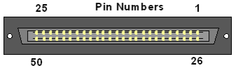
| ■ | Connector Pinouts: |
50-pin Telco Connector Pinouts
|
FXS Phone Channel (Ports) |
Connector Pins |
|---|---|
|
1 |
1/26 |
|
2 |
2/27 |
|
3 |
3/28 |
|
4 |
4/29 |
|
5 |
5/30 |
|
6 |
6/31 |
|
7 |
7/32 |
|
8 |
8/33 |
|
9 |
9/34 |
|
10 |
10/35 |
|
11 |
11/36 |
|
12 |
12/37 |
|
13 |
13/38 |
|
14 |
14/39 |
|
15 |
15/40 |
|
16 |
16/41 |
|
17 |
17/42 |
|
18 |
18/43 |
|
19 |
19/44 |
|
20 |
20/45 |
|
21 |
21/46 |
|
22 |
22/47 |
|
23 |
23/48 |
|
24 |
24/49 |
|
25 for Analog Lifeline |
25/50 For analog Lifeline cabling, see Connecting the FXS Analog Lifeline. |