Replacing FXS Blades
The following procedure describes how to replace an FXS blade.
Power off the device when removing or installing FXS blades.
|
➢
|
To replace an FXS blade: |
|
1.
|
Remove the faulty FXS blade: |
|
a.
|
Identify the faulty FXS blade by the color of its LED, located on the rear panel as described in FXS LEDs. |
|
b.
|
Power down the device, by disconnecting the power cord from the power source, and then unplugging the power cord from the power inlet on the Power Supply module. |
|
c.
|
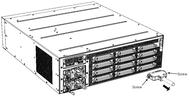
On the rear panel, disconnect the FXS cables from the 50-pin FXS ports on the FXS blade. This is done by removing the captive screws, located on either side of the Telco connector, from the blade's hex-standoff screws, using a flathead screwdriver: |
Removing 50-Pin Telco Connector
|
d.
|
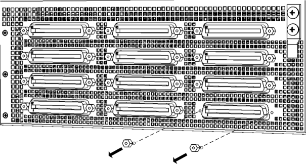
On the rear panel, remove all the hex-standoff screws securing the FXS blade to the chassis, using a 3/16-in. hex-head nut driver. Each FXS port has two hex-standoff screws (7 mm) on either side and therefore, you need to remove all six screws: |
Removing Hex Standoff Screws on Rear Panel (Example FXS Blade S4)
|
f.
|
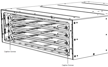
On the front panel, loosen the two Philips-head, spring-loaded captive screws located on either side of the FXS blade: |
Loosening Screws on FXS Blade on Front Panel
|
g.
|
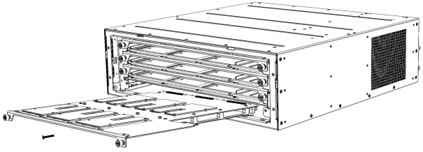
Gently pull the FXS blade out of the chassis slot: |
Removing FXS Blade from Chassis Slot on Front Panel
|
2.
|
Install the new FXS blade: |
|
a.
|
Hold the blade on the front where the captive screws are located, making sure that you do not touch the blades electrical components. |
|
b.
|
On the chassis front panel, orientate the FXS blade as shown in the previous figure. |
|
c.
|
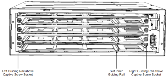
Gently slide the blade into the slot, keeping the left side of the blade aligned with the left guiding rail located above the captive screw socket, and ensuring that the notch on the underside of the blade is aligned to the left of the inner guiding rule, as shown in the following figure. Slide the FXS blade into the slot until it has engaged with the chassis backplane: |
Slot's Guiding Rails for FXS Blade
|
d.
|
On the rear panel, secure the FXS blade to the chassis by inserting the hex-standoff screws (see the figure in Step 1.d for location of screws), using a 3/16-in. hex-head nut driver. Do not tighten the screws. |
|
e.
|
On the front panel, secure the FXS blade to the chassis, by tightening the two Philips-head, captive screws on the front panel of the blade. You can use a Phillips or flathead screwdriver. |
|
f.
|
On the rear panel, insert the hex-standoff screws on the FXS blade, using a 3/16-in. hex-head nut driver. |
|
g.
|
On the rear panel, connect the 50-pin Telco connector cables to the FXS ports of the new FXS blade. |
|
i.
|
Re-connect the chassis to the power source. |