Grounding and Surge Protection
The following procedure describes how to ground the device.
Grounding and Power Surge Protection:
|
●
|
The device must be installed only in telecommunication sites / centers in compliance with ETS 300-253 requirements "Earthing and Bonding of Telecommunication Equipment in Telecommunication Centers". |
|
●
|
Prior to installation, earth loop impedance test must be performed by a certified electrician to ensure grounding suitability at the power outlet intended to feed the unit. It is essential that the impedance will be kept below 0.5 ohms! |
|
●
|
Proper grounding is crucial to ensure the effectiveness of the lightning protection, connect the device permanently to ground (as described in the procedure below). The device's grounding screw must be connected to the equipotential grounding bus bar located in the Telecommunication rack or installation site, using a wire of 6 mm2 surface wire. If the device is installed in a rack with other equipment, the rack must be connected to the equipotential grounding bus bar of the Telecommunication room, using a stranded cable with surface area of 25 mm2. The length of this cable must be as short as possible (no longer than 3 meters). |
Protective Earthing:
|
●
|
The equipment is classified as Class I EN 60950 and UL 60950 and must be earthed at all times (using an equipment-earthing conductor). |
|
●
|
Finland: "Laite on liltettava suojamaadoituskoskettimilla varustettuun pistorasiaan." |
|
●
|
Norway: "Apparatet rna tilkoples jordet stikkontakt." |
|
●
|
Sweden: "Apparaten skall anslutas till jordat uttag." |
|
➢
|
To connect the chassis to an earth ground: |
|
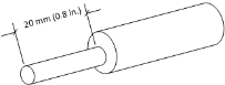
1.
|
Prepare an adequate length (maximum 20 mm or 0.8 in.) of stranded grounding wire (16 AWG minimum size) for the ground connection, as shown in the following figure: |
Stripped Grounding Wire
|
2.
|
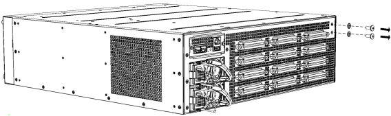
Using a Philips-head screwdriver, remove the two screws and their spring washers for attaching the grounding lug, located on the chassis' rear panel as shown in the following figure: |
Removing Screws and Washers
|
3.
|
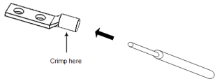
Insert one end of the grounding wire into the grounding lug (supplied), as shown in the following figure, and then use a crimping tool (not supplied) to secure the wire to the grounding lug: |
Attaching Grounding Wire to Grounding Lug
|
4.
|
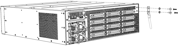
Attach the grounding lug (supplied) to the chassis using the two screws. |
|
5.
|
Attach the grounding lug to the chassis, as shown in the following figure. Make sure that the spring washers are located between screw head and lug. |
Attaching Grounding Lug to Chassis
|
6.
|
Connect the other end of the grounding wire to the building protective earth. This should be in accordance with the regulations enforced in the country in which the device is installed. |