Front Panel Description
The device's front panel is shown in the following figure and described in the subsequent table.
Front Panel
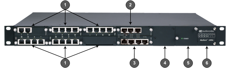
| ● | The previous figure is used only as an example. The number and type of interface modules depend on the ordered configuration. |
| ● | For module slot assignment, see Chassis Slot Assignment for Modules. |
Front-Panel Description
|
Item # |
Label / |
Component Description |
|||||||||||||||||||||
|---|---|---|---|---|---|---|---|---|---|---|---|---|---|---|---|---|---|---|---|---|---|---|---|
|
1 |
FXS, FXO, BRI, TRUNKS, MPM |
Telephony and DSP resource modules:
Note:
|
|||||||||||||||||||||
|
2 |
CRMX |
CRMX module. For more information, see CRMX Module for a description. |
|||||||||||||||||||||
|
3 |
SWX |
(Optional) LAN Extension (SWX) module. For more information, see SWX LAN Expansion Module. Note: The module is a separate orderable item and can be ordered with the device or separately. |
|||||||||||||||||||||
|
4 |
Power 1 |
(Optional) Spare Power Supply module slot. For more information, see Power Supply Module and LED Description. Note: The module is a separate orderable item and can be ordered with the device or separately. |
|||||||||||||||||||||
|
5 |
Power 2 |
Main Power Supply module. For more information, see Power Supply Module and LED Description. |
|||||||||||||||||||||
|
6 |
- |
Extractable Fan Tray module with a schematic displayed on its front panel showing the chassis' slot numbers. For more information on the Fan Tray module, see Fan Tray Module. |