Connecting to DC Power
The device houses two hot-swappable Power Supply modules, providing 1+1 load-sharing and power redundancy in case of a Power Supply module failure.
DC Power Specifications
|
|
|
|
Power Supplies
|
Two redundant extractable power cassettes, hot swappable, load sharing, DC input.
|
|
Input Voltage Rating
|
48VDC, +25%/-15%
|
|
Connector Type
|
Terminal block, 14-AWG wires
|
|
Safety Standards
|
IEC 62368-1, UL 62368-1
|
DC Power Safety Notice:
|
●
|
Connection of the device to the DC mains power must be done only by a certified electrician and in accordance with local national electrical regulations. |
|
●
|
The two DC power sources must have the same ground potential. |
|
●
|
To avoid possible conducted emission interferences, the device should be powered using one of the following options:
|
|
✔
|
AC-to-48VDC filtered power source with a feeding cable no longer than 3 m. |
|
✔
|
Direct 48V battery connection.
|
|
●
|
Connect the device to a safety extra-low voltage (SELV) source that is sufficiently isolated from the mains. |
|
●
|
You must connect both Power Supply modules. Make sure that you connect each one to a different DC power supply source. |
|
●
|
If a failure occurs in any one of the Power Supply modules, replace the module immediately. |
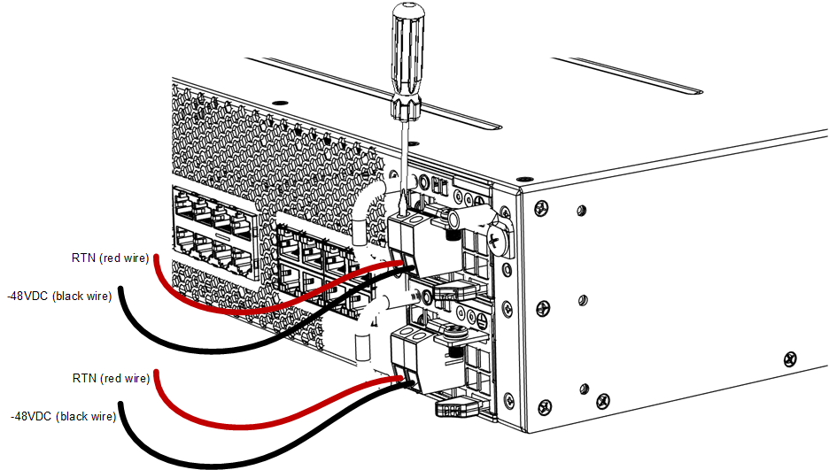
The Power Supply module provides an integrated DC terminal block for connecting two 14-AWG power leads (positive and negative).
|
➢
|
To connect to a DC power supply: |
|
1.
|
Disconnect your DC wires from your DC power source. |
|
2.
|
Using a wire-stripping tool, strip the ends of the two wires (14-AWG) to a length that is sufficient for inserting into the supplied terminal block. Make sure that you do not strip too much of the insulation so that wire is not exposed when it exits the terminal block plug after it has been secured to the terminal block. |
|
3.
|
Identify the polarity (negative and positive) of the two DC power feed wires. Polarity of power feed wires are typically color-coded, where red is positive (RTN) and black is negative (-48VDC). |
|
4.
|
Insert the exposed wire of one of the two DC-input power source wires into the correct opening (according to polarity) on the terminal block plug, as shown in the figure. Make sure that only wire with insulation exits the terminal block. |
|
5.
|
Using a flat-head screwdriver, tighten the captive screw located above the installed wire lead to secure the wire to the terminal block. |
|
6.
|
Repeat steps 1 through 5 for the second wire. |
|
7.
|
Make sure that no wire strands are left outside the connector and that all strands have been clamped under the terminal block screw. Gently try and pull the wires from the terminal block. If the wires become free, repeat Step 5 to secure the wires to the terminal block. |
Connecting Wire Leads to Terminal Block
|
8.
|
Connect the DC power leads to a 48-VDC power source. |