Rear Panel Description
The device's rear panel is shown in the following figure and described in the subsequent table.
Rear Panel
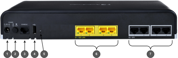
The figure is used only as an example. The hardware configuration depends on the ordered model.
Front Panel Description
|
Item # |
Label |
Description |
|||||||||
|---|---|---|---|---|---|---|---|---|---|---|---|
|
1 |
POWER |
AC power supply plug entry for connecting the device to the external AC power supply adapter. |
|||||||||
|
2 |
ON / OFF |
Power button which powers on the device when pressed in and powers off the device when pressed again (pressed out). |
|||||||||
|
3 |
CONSOLE |
RJ-45 port for RS-232 serial communication with the device. |
|||||||||
|
4 |
|
USB 2.0 port, which can be used for external USB hard drive or flash disk (disk on key) for USB storage capabilities (for example, for configuration file) |
|||||||||
|
5 |
// |
Reset pinhole button for resetting the device or for restoring it to factory defaults. To restore the device to factory defaults, with a paper clip or any other similar pointed object, press and hold down the pinhole button for at least 15 seconds (but not more than 25 seconds). |
|||||||||
|
6 |
S1 (Slot 1) |
Up to four Gigabit Ethernet (1000Base-T) ports (RJ-45) for connecting to LAN network such as IP phones, computers, and switches. These ports support half- and full-duplex modes, auto-negotiation, and straight or crossover cable detection. For a description of the LAN LEDs, see LAN Interface LEDs. |
|||||||||
|
7 |
S1 / S2 (Slot 1 / Slot 2) |
Telephony interfaces, depending on ordered configuration:
|
