Connecting the Ethernet Ports to the LAN
The cabling specifications and procedure for connecting the device to the LAN is as follows:
| ■ | Cable: Straight-through, Category (Cat) 5, 5e or 6 cable |
| ■ | Connector: Standard RJ-45 |
| ■ | Connector Pinouts: |
RJ-45 Connector Pinouts
|
Pin |
Name |
Description |
|---|---|---|
|
1 |
BI_DA+ |
Bi-directional pair A+ |
|
2 |
BI_DA- |
Bi-directional pair A- |
|
3 |
BI_DB+ |
Bi-directional pair B+ |
|
4 |
BI_DC+ |
Bi-directional pair C+ |
|
5 |
BI_DC- |
Bi-directional pair C- |
|
6 |
BI_DB- |
Bi-directional pair B- |
|
7 |
BI_DD+ |
Bi-directional pair D+ |
|
8 |
BI_DD- |
Bi-directional pair D- |
| ➢ | To connect to the LAN: |
| 1. | Connect the RJ-45 port at one end of the cable to an Ethernet port on the SBC module: |
Connecting the LAN Interface
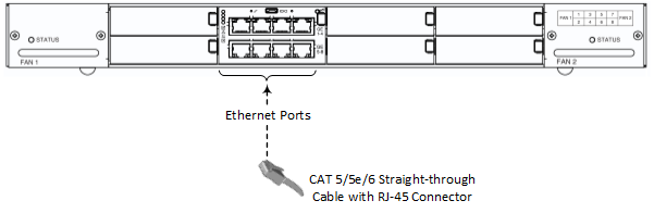
| 2. | Connect the other end of the cable to your LAN network. |
For initial network connectivity to the device, use ports GE 1 or GE 2 to connect to the LAN. These ports (or this Ethernet Group) are assigned to the OAMP interface (192.168.0.2) by default. For port names as well as Ethernet port groups (for 1+1 redundancy), see Deployment of a Standalone Device.