Building and Viewing your Network Topology
The Network view lets you easily build and view your voice network topology entities, including IP network interfaces, Ethernet Devices (VLANs), Ethernet Groups, and physical Ethernet ports. The Network view graphically displays these entities and the associations between them, giving you a better understanding of your network topology and configuration. You can use the Network view as an alternative to configuring the entities in their respective Web pages or you can use it in combination.
| ➢ | To access the Network view: |
| ■ | Click the Network View home |
The areas of the Network view is shown in the example below and described in the subsequent table.
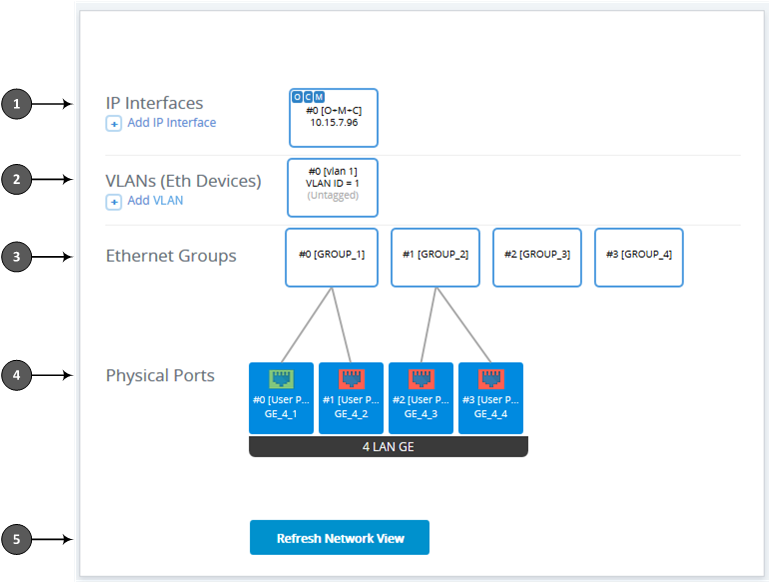
The figure above is used only as an example; your device may show different Ethernet Groups and Ethernet ports.
Description of Network View
|
Item |
Description |
|||||||||||||||
|---|---|---|---|---|---|---|---|---|---|---|---|---|---|---|---|---|
|
1 |
Displays IP Interfaces that you configured in the IP Interfaces table (see Configuring IP Network Interfaces). IP Interfaces appear as icons, showing the application type ("OCM" for OAMP, "C" for Control, and "M" for Media), row index number, name, and IP address, for example:
To add an IP Interface:
|
|||||||||||||||
|
2 |
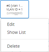
Displays configured Ethernet Devices (see Configuring Underlying Ethernet Devices). The Ethernet Device appears as an icon, displaying the row index number, name, VLAN ID and if its tagged or untagged. If you click the icon, a drop-down menu appears, listing commands:
To add an Ethernet Device:
|
|||||||||||||||
|
3 |
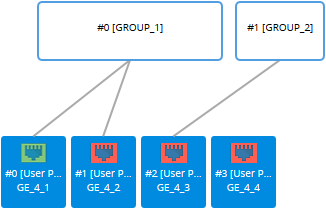
Displays configured Ethernet Groups (see Configuring Ethernet Port Groups). The Ethernet Groups appear as icons, displaying the row index number, and name. Ethernet ports associated with Ethernet Groups are indicated by lines connecting between them, as shown in the example below:
To edit an Ethernet Group:
To open the Ethernet Groups table, click any Ethernet Group icon, and then from the drop-down menu, choose Show List. You can then view and edit all the Ethernet Groups in the table. |
|||||||||||||||
|
4 |
Configures and displays the device's Ethernet ports. To configure an Ethernet port:
For more information on configuring Ethernet ports, see Configuring Underlying Ethernet Devices. The Ethernet ports appear as icons, displaying the row index number, description, and port string number, as shown in the example below:
The connectivity status of the port is indicated by the color of the icon:
To refresh the status indication, click the Refresh Network View button (described below in Item #5). To open the Physical Ports table, click any port icon, and then from the drop-down menu, choose View List. You can then view and edit all the ports in the table. |
|||||||||||||||
|
5 |
If you keep the Network view page open for a long time, you may want to click the Refresh Network View button to refresh the connectivity status display of the Ethernet ports. |


 Green: Network connectivity exists through port (port connected to network).
 Red: No network connectivity through port (e.g., cable disconnected).