Connecting PSTN Fallback for E1/T1 Trunks
The device supports PSTN Fallback. If the device loses power (e.g., due to a power outage or the power cable is unplugged), it automatically routes calls directly (without routing rules) between the Tel side (e.g., PBX) and the PSTN (instead of to the IP network).
PSTN Fallback is supported by specific T1/E1 port pairs, where one port is connected to the Tel side and the other port to the PSTN. In normal operation (i.e., device has power), the port connected to the PSTN is not used because calls from the Tel side are routed to the IP network (and vice versa). However, upon a loss of power, an internal metallic relay switch physically connects the two ports, enabling calls to be routed directly between the Tel and PSTN sides.
PSTN Fallback is supported by the following T1/E1 port pairs:
|
Slot Number |
T1/E1 Port Pairs for PSTN Fallback |
||||||
|---|---|---|---|---|---|---|---|
|
S1 |
|
||||||
|
S2 |
|
||||||
|
S3 |
|
||||||
|
S4 |
|
It doesn't matter which port in the fallback port pair you connect to the Tel side or the PSTN.
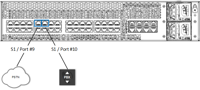
The following figure shows an example of PSTN Fallback cabling, using ports #9 and #10 on the S1 module. When PSTN Fallback is triggered, these two ports physically connect to one another, enabling calls to be routed directly between the PBX and PSTN.